
Homebrew 2.4 GHz 14 dBi Wide Angle Sector antenna |
By Dan Santillan |
 I’ve been wanting to have a sectored antenna, but due to strict policy of importing high-gain antenna in this country, it is very difficult to find a directional high-gain antenna, however; if there is one available it cost a lot, in the US a typical sector antenna cost around 100-200 U.S. Dollar (depending on brand and model) but in this country any antenna can cost more, almost 5 times the price in the U.S. a good example of antenna price here is the d-link 8dbi patch antenna, we all know that this antenna cost under 50 dollars, but here, the same brand and model cost at least 210 dollars (what a rip off!), anyway, I was so desperate to have a sectored antenna, I already build a biquad, double-quad, cantenna etc… I have not missed to build any homebrew antenna I could find on the internet, I’ve done some of my antenna home brewing using a machinery and you could say it is almost a commercial grade, however those antenna I already build doesn’t provide me the beam width I needed, most of the homebrew antenna on the net provides from 5 degrees to a maximum of 80 degrees on horizontal. |
 I’ve been digging the net for a homebrew sector antenna for nearly 8 months and still no luck, until… I found an article in PDF format about the “Planar Omni Directional” written by group of people, the theory of the common omni designs has been explained namely the “Franklin Array (omni with u-shape for the phase , Meanderline Phase (omni with a coil for the phase, similar to aerialix), and the COCO design (an omni with an alternate element soldered together ,similar to grump design) I’ve read the whole article but nothing was mentioned about the sectored antenna and because of my desperation to have a sector antenna I started to experiment different design using the EZNEC antenna modelling program. |
 My initial approach was to design a “Franklin Array” omni antenna because I’ve done the Meanderline with a reflector before and it’s a no performer, I did not try the COCO yet as soldering the joint is difficult, basically this antenna is a centre fed dipole with a “U” shape for shift phasing instead of a coil, so far so good, the design seems to be good but the result was not very promising, the theoretical gain I can get is within 2-3 dBi only!, (aerialix design performs much better than this!) I was not happy with the result so I revised my design again, this time I put a 123mmX123mm reflector at the feed point with a distance of L1/2 from the feed , to my surprise the gain jumped from 2-3dbi to 3-4 dBi! well that is interesting! an increase of 1db (obviously because of the reflector), the sphere also changed from a typical omni pattern to a directional pattern with 30 degrees of beam width horizontally and about 10 degrees vertically, I modify the reflector with different dimension from 1wavelength down to 1/4, after making lots of adjustment which are all based on wavelength, the only size that seems to show a good result is by using the L 1/2 x 1 size, there was no difference with the gain, however the beam width improved a lot! from 30 degrees to almost 118 degrees! my modelling seems to give me a good result, I continue adding more reflector until I reached the top and bottom of the element with an extra 1/4L from the tip of the element, to my surprise the gain increased from 4dbi to 11.5dbi! the beam width stays the same. I’ve check the svwr and it is within the acceptable figure which is 1.2 – 1.5, the design seems to be ideal for a sectored antenna, it is now time to put everything in practice!. I will post all relevant result from the modelling program later on, meanwhile; I will start to make the “sectored antenna”. |
 Without any further ado!… Before we go on, here are the formula. 1L = 300/2437ghz (channel 6 as centre frequency) = 123 mm To start with.. my initial approach for the element material was to use an electrical copper wire with a size of 2mm in diameter, I found one and I start to bend it based on “Franklin Array” theory using the waveguide for my element size, after the bending work I found out that the wire is too soft and it won’t stand straight so I scrap it, I went to my backyard and I found a copper plated welding rod with the same diameter, the rod is hard to bend (which is good!) and the only thing I hate with it.. is it takes a lot of curved at the corner edges ( approx. 2mm), I have to adjust my measurement and deduct the edges size to give me an exact element size, instead of bending the wire at 30.5 mm I bend the wire at 28.5, the result was exactly 30.5 from the tip of the wire to the edge of the corner. (the element dimension will be at the bottom of this page), I made two elements. |
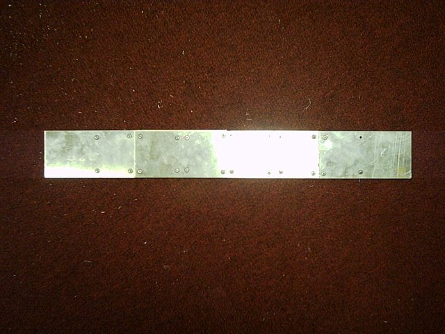
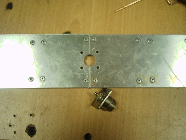
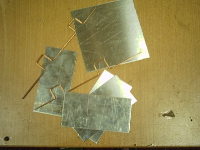 My first idea for the reflector is to use a strip of tin can or a brass sheet, I already have this material at hand so I started making it, I cut a size of 61.5mm x 495mm (the actual length should be 492mm or 1 wavelength x 4) but I added another 2 mm for the connector space, then I drilled a hole in the middle for the N-Type connector, after making it and mounting the connector I am not satisfied with it as it tends to bend in the middle, both material is too heavy and it bends (with the connector attached), I went to buy some pcb board but the store do not have a board a size of 61mm, all they have is a pre-cut of 40mm x 40mm only, this is another setback for my project, instead of giving-up, I found 6 pieces of my unused 1mm aluminium plate from my previous project (biquad project) the aluminium was already cut to 123mm x 123mm (I almost throw it a week ago!) anyways, I only need to cut the aluminium to 61.5mm as the length is already 123 mm, I cut 4 pieces of it, I kept the excess part for joining them together, I drill a hole in each corner and attached it at the back for support then I use rivet to bolt them together, after doing all riveting (which is a real pain) I drill a hole in the centre, I was very surprised with the aluminium reflector, it doesn’t bend it is lighter compared to tin and brass ( I guess this is the way to go!) I reckon the excess aluminium that I use to support the backside to join the plate helped the whole structure not to bend, I am not sure if using a whole two 61.5 x 123mm of plate on the top of each other will provide the same stiffness, I will try it later when I get a chance to buy a big size aluminium plate. |
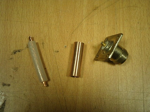
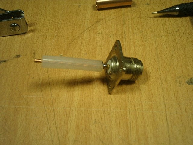
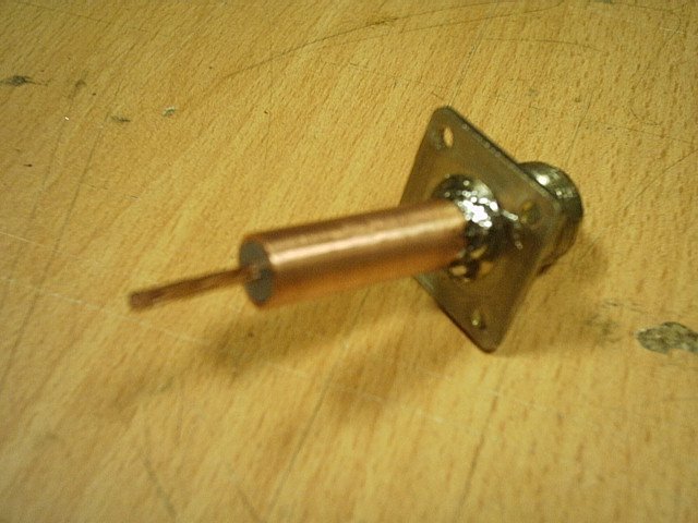
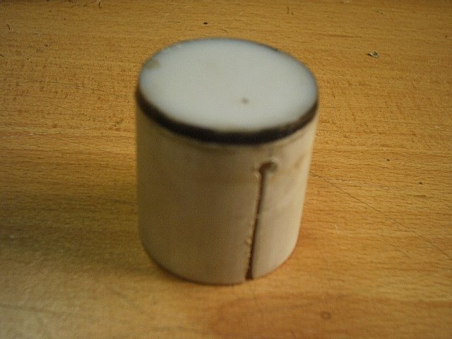
 At first I thought of using a rigid coax cable such as RG213 as a feed line directly connected to the element but I was worried it will not hold strong, instead I opted to use a N-Type connector, For the feed line I cut a 29mm length of copper tube with an outside diameter of 9mm and inside diameter of 8mm, then I cut a 45mm RG213 coax cable and removed the outer shield and the braid shielding, I solder the coax I prepared to the centre pin of the N-Type connector, (make sure to solder it on the pin as close as possible. After soldering the coax, I inserted the copper tube and solder the whole edge at the base of the N-type connector. |
|
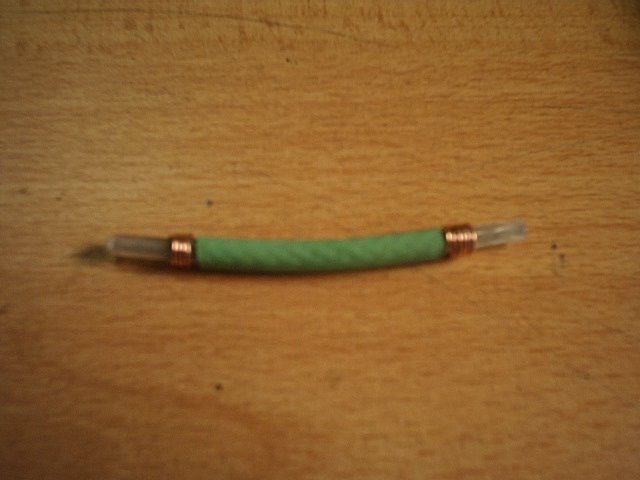
 The article mentioned that the “Franklin” antenna is unbalanced type and a Balun is required for proper impedance (I can tell it is unbalanced as the other element is connected to the ground shielding), my idea to make a balun is to use a L1/4 of 50 Ohms coax and tapped it at the feed point, my first candidate was the RG213, after cutting it to the size I need, I bent it but the damn thing is too hard as the wire and the shield is too thick! and instead of fighting with it, I decided to use the RG58U, This time I use different approach, instead of using a 1/2L for its size, I read in an article about balun making and it was suggested that the velocity factor must be added to the wavelength size, the velocity factor of RG58 is 0.66, so after doing the math I come up with a size of 40.5 |
|
Formula for size adjustment Length = L1/2 x VF ( 61.5mm x 0.66 = 40.59) After I made a 40.5mm of RG58 it is still hard to bend it because of the outer shield, I solder it at the feed point and this is what it looked like. |
|
|
|
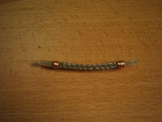
 I am not satisfied with the result of it and the way it looks, it is untidy and it looks like it will not last, I redo the balun again, this time I cut a 50 mm of RG58 and then I remove the outer shield, I trimmed the braid shield to a size of 40.5mm and then centred it, I wrapped the braided shield’s both end with a solid wire that I took from a Cat-5 cable. I slipped a shrink tubing and solder both end until the whole solid wire is covered with lead. |
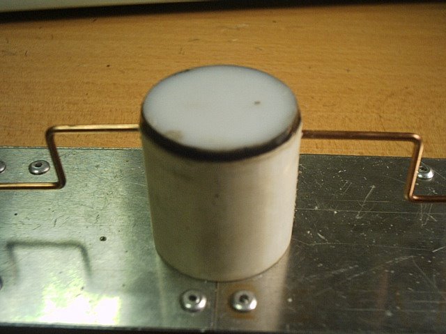
 Solder the balun at the feed point, this process seems to be a lot more easier, cleaner and looks like it is strong enough. |
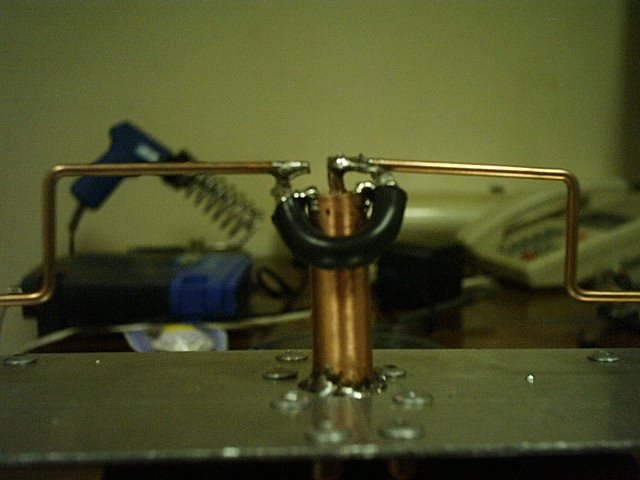
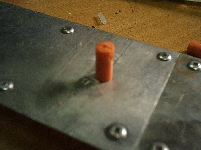
 The first element is soldered at the centre pin and at the copper tube (right side of the pic) the other element is soldered at the centre pin of the balun, the distance of the centre pin from the reflector is 30mm, after soldering the two elements there is a 10mm gap from the “U” shape to the reflector and there must be something to support it like a stud or something. |
|
|
 I use a plastic tube that I got from my daughter’s playroom (a plastic xylophone stick) cut them in 15mm size, drill a hole underneath and another hole at the side (the hole must be 10mm from the bottom) then make a slit enough for the wire to get through. |
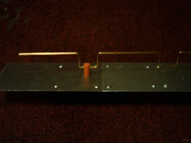
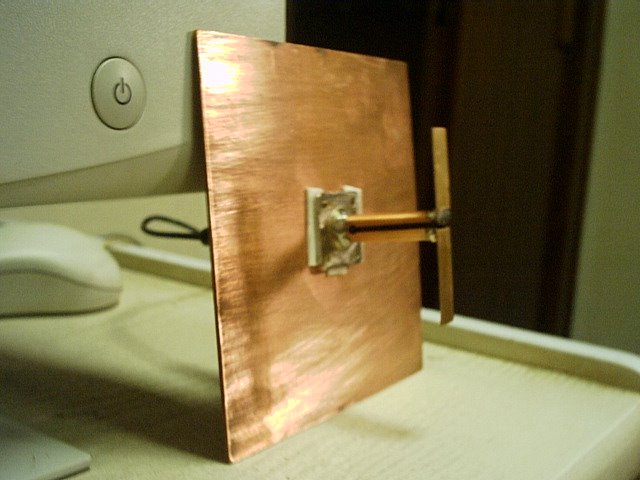
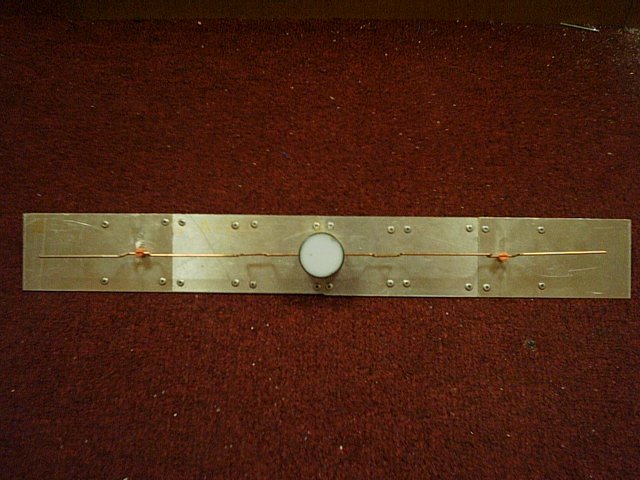
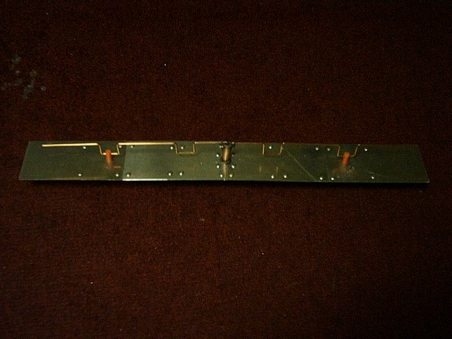 The Final Naked “Sectored Antenna” |
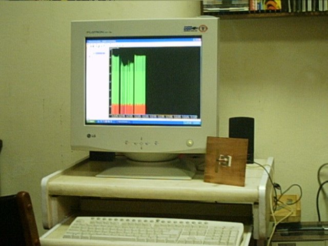
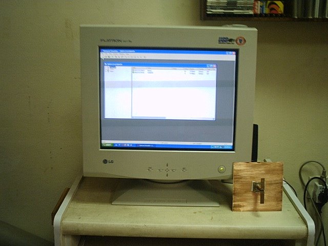 The Moment of Truth… After spending 4 hours of building the “sectored” antenna it is now time to put it under test and see how it performs. I setup a facility to test the antenna. Client Setup. |
 Windows XP SP2 Netstumbler PCMCIA PCI Adapter Avaya/Orinoco PCMCIA Card 1.5 meters pigtail Homebrew Dipole antenna with 123mm x 123mm PCB reflector approx. 2-4dbi gain. |
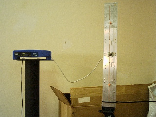 The “Sector Antenna” under test, connected to a Linksys WRT54G V2.2 with DD-WRT V22 Final Firmware, the transmit power is set to 20mw only and set to use the right antenna for both TX/RX, the pigtail is a 1 Foot RG58 50 Ohms and the distance of the antenna to the client PC is approx. 6 meters, I don’t have a large space to conduct the test and that is why I reduced the TX power to 20mw. I use the WRT54G stock omni antenna for comparison against the “sector” antenna. |
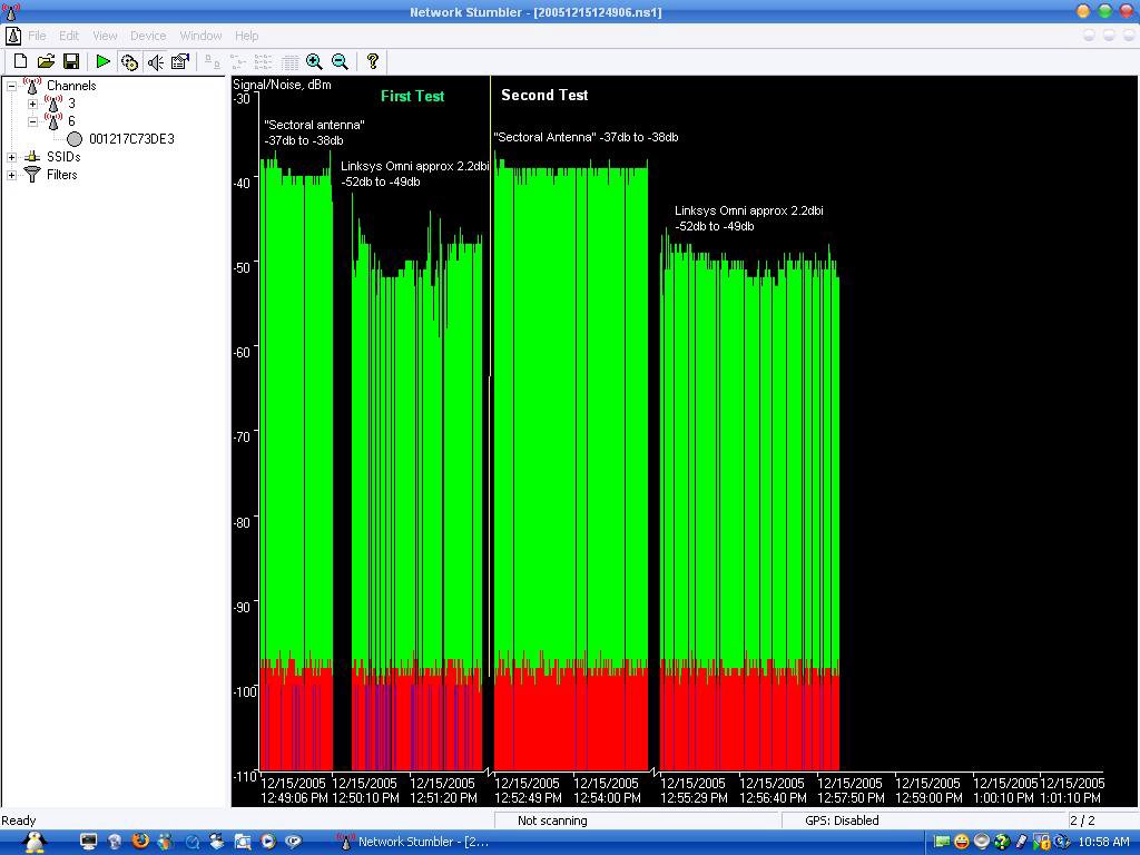 My first initial test shows a good result, the “sectored antenna” was focused directly to the client antenna, it clearly shows that there is a 13-14db difference against the Linksys stock omni antenna, I’ve done two test to see if there is any changes while replacing the antenna, each time I replace the antenna I paused the Netstumbler first, I was very impressed with the current result, the EZNEC simulation predicted an 11.5db gain, so far I am getting this result from a close proximity of the AP and the client, I am not sure if I would get the same result on a open space which I will do if my time permits, for now the result is quite good and I am satisfied with it. I also performed another test for the side lobes. |
 This is the result , sorry if I have not screen capture it I am getting lazy do it right now, anyway, on the first graph the antenna is facing to the left @90 degrees (client antenna at 0 degree) I am still getting the same figure of -37db , the centre graph is the stock omni antenna which is within the same result of my previous test, the last graph shows the same figure but this time the antenna is facing the opposite direction, again I must stress that I’ve done this test at a close proximity and I know that there are reflected signal coming from the wall of the room, I will do an extensive test on an open space later on and I will update this blogsite for further result and on my last test I face the antenna’s backside towards the client antenna, the result is -68db, it seems that there is a huge drop, however, while the antenna’s backside is facing the client the antenna’s front is also facing the wall and for sure there are reflected signal that is arriving at the client antenna, again this is not an accurate result. |
|
For now, this antenna seems to perform good but who knows??? I will do the test later on, I am planning to install this antenna at the front door facing towards my backyard, that way the signal is concentrated only within the premises of my house.
My friend suggested that I should put it in an enclosure which I agree with him, however, I was too concerned about the loss in gain after enclosing it, he suggested that I should use an electrical plastic trunk (the square plastic that is use to keep wires) I also agree with him however I don’t have the material at hand. |
 I found a vacuum plastic tube (not the hose) with a diameter of 35mm and 1 mm thick, instead of using a plastic trunk I cut a size of 35.0mm, then I drill a 2.5mm hole and a slit at the side then I use a piece of acrylic to cover the top and glued/epoxy it, my plan for this is just to cover the feed point and let rest of the elements exposed (I hope that this is a good idea :-)), since the elements are exposed I might spray paint the whole antenna with a water resistance paint (appliance paint). |
|
 The Final “Sectored Antenna” with a tube cover. (this thing looks like a miniature orbiting satellite), anyway, I have not done a test with a tube at the feed point, I will do that later on, for now, the antenna is in action and it covers the whole premises of my house down to my backyard and there is no signal at the outside of my front house which is good and my it’s intention. To be continued….. |
You must be logged in to post a comment.
Help us continue our work with a donation
 Forum {beta} Forum {beta}Hatch ideas and help others with their ideas. |


20 queries. 0.132 seconds
November 28th, 2005 at 14:34
Wow! very impressive.
I’ve build several antenna for wifi but have never found a design for a sector before.
I look forward to you long distance results.
Dan
November 29th, 2005 at 17:59
Got the idea, I am building a sector antenna based on your design, but will be using a different radiating element.
January 14th, 2006 at 16:42
I too live in Saudi Arabia, Rabigh is home for me, Facing the same problem, need 150 metes of WIFI coverage. Any help or joined support, would be great.
Regards
Lamar
April 12th, 2006 at 23:42
What is the dimension of center element copper wire.
May 9th, 2006 at 16:31
What are the dimensions of center element.
May 23rd, 2006 at 13:25
Great job guys… Thank for you work…
June 11th, 2006 at 17:35
Perhaps you should put a link to the original design ?
http://www.qsl.net/yu1aw/vhf_ant.htm
June 15th, 2006 at 1:03
@foobar
what makes you think that the link you provided is the original design? are you aware that the 4NEC2 has a template for that particular design? are you also aware that i have the pdf documents the chap did mentioned? he clearly states how he did his and none of your so called “orginal design” has the same dimemsion he used, although it has the same design look. That doesn’t mean he copied it or got the idea from your so called “original” design.
incase you are not familiar with the things i mentioned, STFU.!
give the chap some credit.
June 25th, 2006 at 6:26
Great.
Can we increase the gain by increasing the number of elements.
July 17th, 2006 at 20:53
My first project was a radio telescope 10 years ago, now I would like to build something that is
VERY directional and can send and recieve to and from wifi devices with a range of over 2km
what type of antenna is required I would rather build the thing myself if possible
Please help
August 14th, 2006 at 16:29
Did yoy see amos 9 sector antenna? http://www.qsl.net/yu1aw/vhf_ant.htm Ithink it is a good antenna, i have made one and it works better than pacific wireless SA24-90-17 antenna, and i did not make it with perfect reflector. If some one try to make one i have interesting solutions for easyer making, contact me one zoran.s@verat.net.
August 19th, 2006 at 12:15
I am going to build it soon and let gives u the result