
VoIP DECT and analogue phones on OSS Linux soundcards using Asterisk
|
By Onno |
Table Of Contents
Architecture
Hardware ‘hacking’
First approach: transformers
Second one: Direct modifications
Coupling at the right locations
Speaker
Microphone
Ring tone detection circuit
Changes to the Asterisk OSS driver
The driver / Download
DTMF detection
Stereo support
Ringing
Off hook/hang-up detection
Software setup
Configuration/module load
Mixer setup
Setting the thresholds and timeouts and volume prescaler
Dial plan issues
Important things
Links and Acknowledgements
The phone
VoIP is ‘in’ and very often ridiculously cheap. Most commercial PC-to-phone adapters (DECT as well as POTS) are still rather expensive in the 100EUR range. That is quite a lot of money considering that a phone often costs only 10EUR (eBay etc.) or is essentially even for free when there is an old one lying around.
Now a sound card is often also lying around and even if not, both items together will probably cost less than 20EUR. And modern sound cards are equipped with everything needed to connect to a telephone in principle, i.e. simultaneous high-quality analogue input and output.
But there are some problems: The voltage levels of a typical sound card in respect to the telephone system are totally wrong and a phone needs a DC voltage to operate and go off-hook. Also, there is no proper software support for a phone that is connected to a sound card.
But usually, one still needs to dial via the PC’s keyboard and not the phone’s keypad, there is no ‘hang-up’ or ‘off hook’ state for the phone (i.e. no dial tone), and the PC needs another channel (visual message on screen or another sound card) to indicate a ringing phone.
The following text describes the hardware modifications and all software changes (so far…  necessary to the asterisk open source PBX to get a DECT phone connected to the PC’s sound card going, complete with dial tone, DTMF detection (i.e. touch tone dialling) and ringing the phone. The on/off hook state of the phone will be detected by the modified asterisk driver, too.
Asterisk itself also fully supports protocols such as SIP so that you can connect to a SIP provider (web.de, sipgate etc…) with your PC. This can happen automatically and in the background so that it seems that you have just another phone connected to a regular phone provider.
To make things clear again, this page describes a modified version of the asterisk chan_oss.c Linux OSS sound card driver for asterisk, NOT the original version!
Don’t be afraid, the changes are trivial. But if you have any doubts, consider asking someone with enough experience to do this
Note that most of the modifications here (except the ring generation) are described in more detail and variation on this fine page here. There are pages both for the non-invasive and the modification method.
This has been tried out but does not work very well. Try the second approach instead.
The most straight-forward approach to interfacing the sound card with the telephone is of course a physical interface between the sound card and the phone without any modifications to the phone. Note that this approach is only possible with sound cards which possess a power amplifier onboard! The power amplifier is often visible as a separate DIP(-like) chip next to the slot cover and the sound cards main IC. An alternative is to use an external amplifier, of course.
For this approach to work, two important things have to be ensured. First, the sound card must generate a rather high voltage (10s of volts) to let the phone ring. Second, it has to generate a constant DC voltage so that the phone detects it is on line and this may be even needed (in the case of the phone I used) just to get the microphone and/or speaker functioning.
These two things are possible for example with this circuit:
With both transformers being small 230V (110V) <-> 6V…12V ones from the junk box, the capacitor being rather big (1000s of uF) as it acts as power supply filter here, and the diode any 1N4007 or whatever. Phones behave rather symmetric in respect to the line that feeds them, more about this can be read here.
The upper transformer T1 is driven by the left channel of the sound card and feeds the voice into the phone. Transformer T2’s sole purpose is to generate a constant DC voltage at the capacitor on the secondary side. T2 is therefore continuously fed with a sine wave from the sound card, in the 50-60Hz range (whatever works best for the combination). The phone’s output signal is picked up on the secondary side of T1 (works best) and fed into the sound card using the (here optional) coupling capacitor and maybe an additional resistor in the phone line. As all parts used here have a high enough internal resistance, it should work without the R. If you want the phone to be on floating potential in respect to the PC (generally a good idea…), replace the ground connection between the secondary and primaries with another cap.
With proper tweaking, the thing worked somewhat, but a few problems popped up:
So much for that ¤śÉ
Second one: Direct modifications
Directly modifying the phone/DECT base station has various advantages. IMHO, the most important is the nearly 100% removal of those annoying echoes from the voice stream. As the DECT phone I used had separate analogue channels on the DECT controller for input and output, the echo problem shrank to the level of acoustic cross talk from the speaker to the microphone in the headset, which is, with the proper settings hardly audible even without using any further digital echo cancellation techniques.
Coupling at the right locations
First of all: Coupling the phone to the sound card should be done only using capacitors, not directly as it is shown on the GRYNX
pages. Ignoring this advice may very well damage your PC, sound card and/or phone.
I won’t go into much detail here, but this worked well: Disconnect the phone from the line, power it only with the wall brick (For ringing the phone, you need one that is self-powered with a wall brick). Ring voltages may be dangerous (see also the other pages). Never fiddle with the official phone line, that’s both dangerous and maybe even illegal. Do the following only if you’re 100% sure if you know what you’re doing.
Pick up the phone and listen for any, even very quiet changes in what you hear. With your finger roam around the phone’s PCB, especially around the bigger ICs (in the case of DECT, except the RF parts, that is close to the antenna) and touch the legs of the ICs with your finger. If there is a slight buzz, you have found the right location and you can reduce it to one single pin. There may be multiple such locations. Take the output of your sound card, insert a small capacitor (or two small ones in for each wire to be 100% sure) play music on your PC and try to get it playing on your phone. The sound should be clear and undisturbed, though phone-like (that is, audio frequencies above 3-4kHz are capped).
For the signal path phone -> sound card, take the sound card’s input, add small capacitors, set your mixer setting in a way such that you hear the usual buzz if you touch the input and roam around on the phone again (this time with the other pin of the capacitor of course). You should be able to locate the audio output of your phone like above.
This is a bit harder as it requires to insert a not-so-small voltage into your phone. If you have an oscilloscope, the situation is much easier here. If not, invent your own procedure
Hang the phone up. Generate a 50Hz signal and feed it into the usual phone jack. Add a DC offset wit the same value as the peak to peak voltage of your ring AC (Works for me, maybe you should be able to slowly adjust and increase both the AC and the DC parts in your ring setup…).
This, of course,
does not mean that you should connect your phone to mains voltage!
Start with 0V. Increase the amplitude up to about 40V. At some voltage level, the phone should ring. If it does not, then it may be the case that your phone requires a different ring frequency or even waveform. Although phones are seemingly specified (see section “Signalling/ringing signals”) to run with a rather broad range of ring voltages and frequencies, the phone I used was very picky and needed exactly 50Hz to ring.
I found this out after playing with the nice sound tool audacity under Linux for quite some time. The asterisk driver modification (see below) so far is only set to 50Hz ring frequencies (and square waves seem to be best), if you need a different one, ask me or simply send a patch-patch
Assumed that the phone rings at 50Hz, the hard part begins, the search for the low-level input into the DECT phone for the ring voltage. If you have the oscilloscope, search for (smaller) AC signals on the phones PCB as the phone rings. The ring AC detection circuit probably resides in an IC. If you think you found the right location, insert a small 50Hz AC level there (capacitor – and diodes, see below). Some day, you’ll get the phone to ring! :-))
It should be noted, however, that the ring tone detection circuit may have an digital input – so you should properly cap the voltages using diodes to prevent damage to the chip.
You can get a 50Hz square-wave-full-amplitude-on-right-channel-only signal here.
Changes to the Asterisk OSS driver
Asterisk is an ‘open source full featured PBX’ (private branch exchange). I.e. something that you can program so that it happily switches hundreds of calls for you, handles SIP/other VoIP and ordinary lines and everything in parallel. To continue, you should know what Asterisk is and how to setup/configure it. If you’re searching for a ‘sip softphone’ here, you’re right in the sense that asterisk can do the same things (and much more), but without a clumsy GUI.
Several changes to the driver were necessary. I tried to make them general enough so that the modifications should work for more people. You can get the patch to the driver here. A precompiled shared object that you should be able to put into /usr/lib/asterisk/modules can be found here: chan_oss.so. This should at least work in Debian/Testing. If it works, it should be sufficient to put this into the mentioned directory, fire up asterisk and do a “load chan_oss.so”. I’m working on renaming the methods etc. so that this can be used in parallel with the OSS driver (Which should provide a nice testing facility in this case).
Important: For proper DTMF detection, set
OPTIONS += -DRADIO_RELAX
in the Makefile. It is already there but commented out!
By default, the asterisk OSS driver does not detect inband (that means: ‘in the voice stream itself’) DTMF tones. For some odd reason that I still do not understand entirely, DTMF detection is the driver’s task and not a task for the core of asterisk. Only a few changed lines were needed for this. The necessary code is partially copied from the modem drivers (chan_modem.c and the like).
The driver’s output format has been changed from mono to stereo to support the extra ring line. There are some checks to see whether a ring signal or another condition is played. These changes still need some cleanup, i.e. no symbolical constants, direct testing for numerical values etc…
With the hardware setup as described, generating the proper ring signal is straight-forward. As the driver already has a table with sounds to play to indicate various conditions, only a change of the ring tone to an icky 50Hz buzz was necessary.
This was, by far, the hardest part in the driver. As there is no separate signal coming into the PC that tells the driver whether the phone is off hook, the audio input signal itself needs to be checked for sure signs of a picked-up phone.
My idea here is as follows: If the phone is hung up, no noise from the microphone and its amplifier enters the sound card. The sound card more or less only sees its own noise. In this state, the noise power level is very small.
If the phone is picked up, the microphone and its amplifier is connected (either electronically or electromechanically through a relays) to the input line of the sound card. A lot more noise and background sounds will enter the sound card. The difference to the hung-up state is (at least in my case) clearly distinguishable from the picked-up state. This enables off-hook detection without any additional components.
It should be noted here, though, that this may fail if one presses the ‘mute’ button on the phone as this may essentially do the same thing to the noise levels as a hang up. I consider this only a minor flaw as I normally don’t use that functionality.
The figure below illustrates this concept, you can see there two drawings of artificial ‘amplitude histograms’ made from the sound card’s sampled signal. By amplitude histogram, I mean a histogram of the sound card’s sample values for a given period of time. I.e. what results if you project those nice time-axis displays of sound data in your favourite sound tool to the screen’s Y-axis.
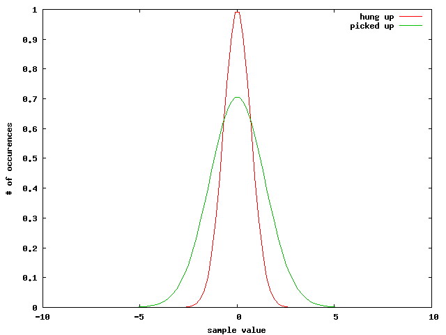
The red one should depict the phone in hung-up state with little noise and therefore a sharp peak around zero (or your sound card’s ADC offset, this is often not identical to zero!). The green one depicts the noise in picked-up state, broader due to the additional noise. By measuring the width (~ standard deviation of the peak), it is possible to determine the state of the phone.
The noise going into the signal really gives a nice Gaussian, btw (As one would expect!).
To make this process more reliable, a few additional things are implemented in the modifications. The first and important one is that the off-hook detection must be a lot more insensitive during phone rings. Else, when the phone rings, a lot of cross talk would trigger a pick-up indication, which is obviously not very practical for the phone user… except you’re sitting next to the phone for all the time.
The other one is that there is an detection hysteresis, meaning that a certain value is needed to trigger ‘picked-up’ state and a certain value explicitly below that is used to trigger the driver into ‘hung-up’ state.
And, last, there is code that checks if a number of times the threshold must be crossed before the trigger gets really activated. This acts as some form of a low pass filter to prevent miss-detections due to spikes and aliasing effects (the sound input is analyzed block-wise).
This will sound as a bit awkward method and maybe even as an unreliable solution, but so far it works for me! I’m not sure about any long term drift of the sound card but even if such things occur, it is rather easy to re-adjust the values in the configuration files (see below). The only drift I have noted so far is slightly increasing noise as the PC warms up. This is completely normal from the physics standpoint, but it is also nice to see that in reality
As stated above, the compiled chan_oss.so module can simply be copied into the /usr/lib/asterisk/modules path. This is also possible with an already installed asterisk (in the current state, you will replace your old OSS driver, though!), simply compile asterisk in your home directory (without “make install”) and copy the file from channels/chan_oss.so then.
To load the module, put
load => chan_oss.so
into your modules.conf, as usual. Currently, the driver distinctly differs from the old chan_oss.so that it does not support auto-answer shell commands. If they are not there, you have the modified driver.
Without the asterisk driver being enabled (and thus blocking the sound card), you can fetch and play the 50Hz square wave starting at low volume. By gradually increasing the volume, you should be able to find the spot where the phone reliably starts to ring. This is the output volume setting which is right for asterisk. Save this setting so it can be restored before the start of asterisk each time.
A neat tool do this is aumix. With the command
$ aumix -S
a file ~/.aumixrc is created (you can use the ‘-f’ option to specify a different file name, see also ‘aumix –help’ as usual…) which contains all mixer settings. These settings have to be restored later on with
$ aumix -L <filename>
Write this into your /etc/init.d/asterisk start-up script, for example.
Setting the thresholds and timeouts and volume prescaler
All the following settings have to be made in the file
/etc/asterisk/oss.conf. The specified configuration variables here all need integer arguments and have to be set in the
[general] section of this configuration file.
After checking that the driver at least loads, the next thing to do is to enable asterisk to output the current ‘standard deviation’ value of the amplitude histogram detection function to the console. This is done by setting hd_disp_interval to a value different to the default of “-1” (no output), for example hd_disp_interval=30.
By the way, it is advisable to call asterisk with
the command line arguments
$ asterisk -f -c -d
to get a shell where things can be tried out. After enabling the stddev display, some numbers should appear onscreen which should change with a) hanging/picking up the phone and b) speaking into the phone, like described above.
Note the differences between hung-up and off-hook. Write down the values. Now, set hd_hl_threshold, the pick-up threshold level, to a value just below the observed values when the phone is off-hook but no one is talking. Similarly, set hd_ll_threshold to a value just above the value that appears when the phone is hung up. The variable
hd_hl_ring_threshold is like hd_hl_threshold but used when the phone is ringing, i.e. there is cross talk on the input. Set this a bit higher than hd_hl_threshold.
After restarting asterisk, there should be messages that the phone has been picked up or hung up. If this does not work reliably, try to increase the values for hd_hl_seqmin and/or hd_ll_seqmin respectively. The detection will be a bit delayed to the actual action; this will increase with the values for *_seqmin. But normally, they should be still small enough to not cause any headaches.
If this works ok, try to use asterisk’s example dial plan (that with the demo application and long introduction speech). DTMF detection should work. If it does not, check the value of “-DRADIO_RELAX” in asterisk’s Makefile.
Try to test the complete signal path by dialling the echo application (600). There should be at most slight echoes. If there is too much echoing which you can’t reduce by your sound card’s mixer settings, use the configuration variable vol_divide to scale down the input signal received by the driver before it is given to the other parts of asterisk. The default variable for this is 3, which works well in my case. Addition, 10/12/05: Note that I built a potentiometer into the phone to weaken signals, but this is more or less a relict of investigation. In all but the most extreme cases, this should be unnecessary with vol_divide or, perhaps further modification of the driver for throttled output.
Having a working phone is good, but the standard configuration of asterisk isn’t exactly what one wishes for a regular telephone. As a clear indication, there should be a dial tone which should be switched off after the first digit dialled and maybe one also doesn’t like the drivers busy and congestion signals.
Asterisk has the dial plan for this, but please see the details for yourself in the appropriate documentation. After one has grasped the idea, configuration of the dial plan (in extensions.conf) is easy and straightforward.
A useful asterisk application for generating the dial tone is
Playtone, which has to be called for example with
Playtones(dial). Contrary to what is stated in the documentation of the Playtones application, it has to be called as
Playtones, not Playtone.
A simple extension map (+ all necessary includes etc. not shown here) that works could be similar to this:
[default]
;
; Default context
;
exten => s,1,Playtones(dial) ; start with dialtone
exten => 0,1,StopPlaytones ; dialling ‘0’ stops dialtone and
exten => 0,2,Goto(dialing1,s,1) ; goes to the ‘dialout’ context
exten => 1,1,StopPlaytones ; ‘1’ is a speed call
exten => 1,2,Dial(SIP/girlfriend,,rg)
exten => 1,3,Goto(prehangup,s,1) ; special handling after hangup
exten => 2,1,StopPlaytones ; and so is ‘2’
exten => 2,2,Dial(SIP/parents,,rg)
exten => 2,3,Goto(prehangup,s,1)
exten => 9,1,StopPlaytones ; ‘9’ calls the echo application, the text below is
copied from the example
exten => 9,2,Playback(demo-echotest) ; Let them know what’s going on
exten => 9,3,Echo ; Do the echo test
exten => 9,4,Playback(demo-echodone) ; Let them know it’s over
exten => 9,5,Goto(prehangup,s,1)
exten => i,1,Goto(prehangup,s,1) ; busy and wait for hangup – nothing more
exten => t,1,Goto(prehangup,s,1)
[dialing1]
;
; context while dialling out
;
exten => s,1,DigitTimeout,2 ; really dial 2 sec after the last digit
exten => s,2,ResponseTimeout,10
exten => t,1,Playtones(busy) ; If nothing happens
exten => _X.,1,Dial(SIP/${EXTEN}@myprovider,60,rg) ; dial
exten => i,1,Playtones(busy) ; happens for single digits
[fromsip]
;
; context reached from outside
;
exten => _X,1,Dial(Console/dsp,30,rg) ; simply dial the console (i.e. the phone!)
[prehangup]
;
; context after a call/action
;
exten => s,1,StopPlaytones
exten => s,2,Playtones(busy) ; hang your damn phone up!
exten => s,3,Wait,36000 ; wait 10h and then maybe give the driver’s busy signal
exten => i,1,Goto(prehangup,s,1) ; invalid number
exten => t,1,Goto(prehangup,s,1) ; timeout
If you want to connect a lot of people, your dial plan will surely look completely different Of course, a separate configuration of Asterisk’s SIP support is usually necessary, too.
Contact me if you have any questions (email address at the end of this page).
Do not choose the very cheapest sound card brand, or better, check if the sound card
Stay away from the RF/high frequency/radio parts of your DECT base station. Changes there may affect your RF signal quality, detune your DECT to non-allowed frequencies, decrease range, whatever.
For non-DECT analogue phones (compared to DECT they’re really impractical, but maybe you’re staying with them for the one (privacy) or the other (EM mind control waves) tinfoil-hattish reasons ;-P), you have to make sure that the ringing circuit gets its voltage from elsewhere, so use a phone that is power by a separate wall brick and not the phone line itself. As said above, the ring-voltage-generation is not as simple as it seems.
After all, remember that I take no responsibility for these modifications!
Keine Gewähr, keine Haftung! All trademarks are the property of their respective owners.
Oh I hate disclaimers!
As said above, I can only recommend this page, it explains phone <-> sound card connections in detail, as well as the required levels for phones, the most important thing when further modifications to the shown circuit ideas are needed.
Then there is this Grynx page which explains nearly all of the hardware modifications I describe here in a lot more detail.
The FLOSS product everything here depends on, Asterisk from Digium.
|
|
|
|
|
|
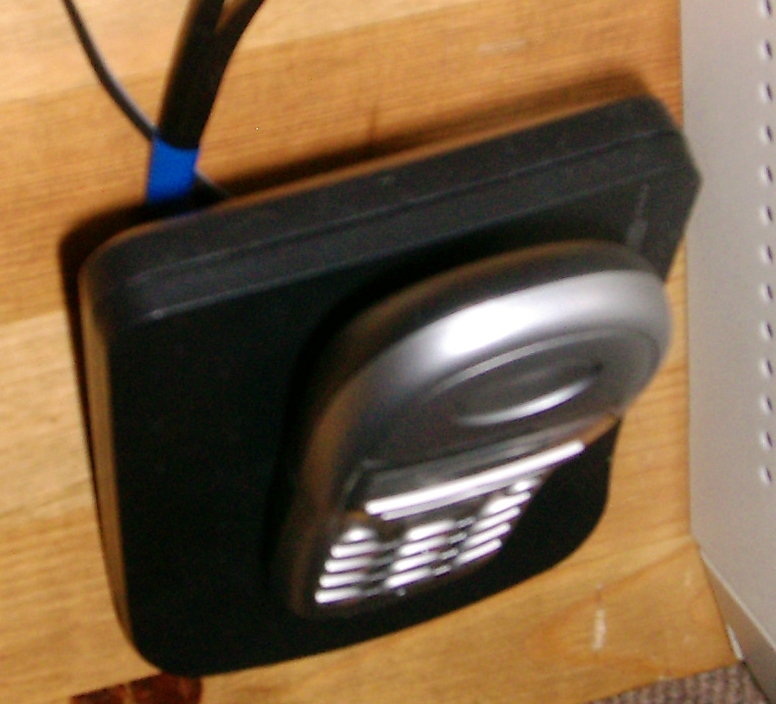
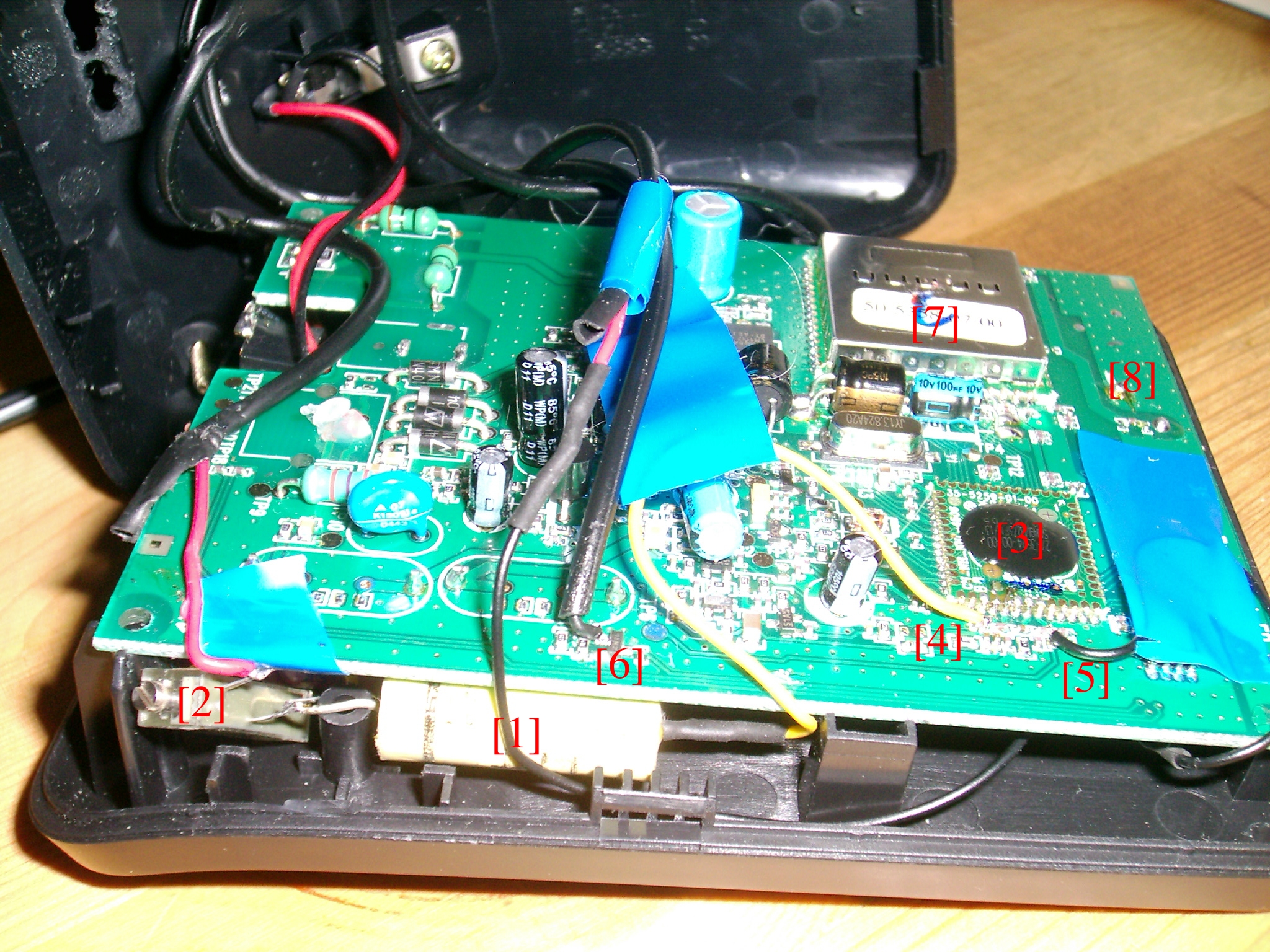
Description to the notes on the last picture:
* [1]: One of the capacitors used for DC decoupling. There are two of them, but the other one is hidden below the PCB (on the right side).
* [2]: (Optional) potentiometer to reduce levels into soundcard
* [3]: The integrated circuit in this phone that does all the DECT processing and AD/DA conversion.
* [4]/[5]: Output from and input into phone.
* [6]: Connection to ring detection. There is still one transistor between the wire and [3].
* [7]/[8]: Radio front end and antenna. Do not touch this.
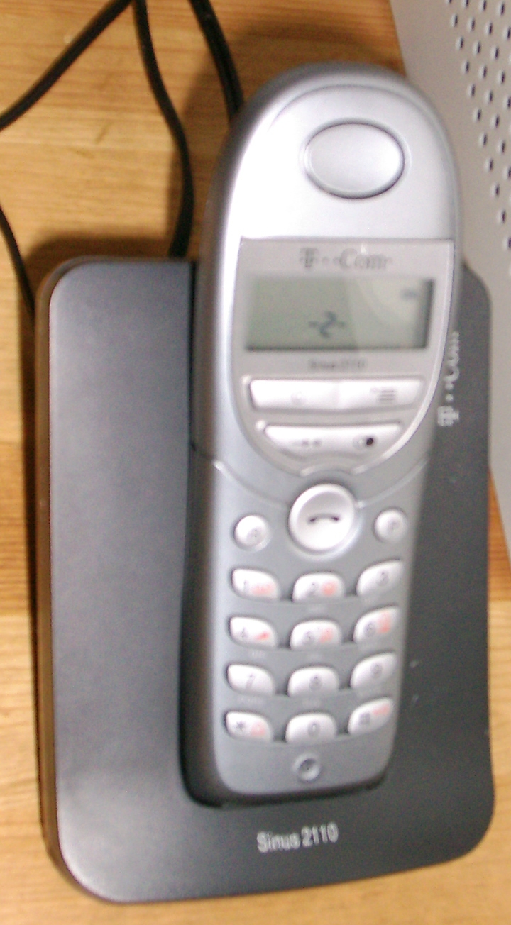
The phone used is a T-Sinus 2110. Some interesting thing to note about this phone:
* Cheap and good
* At least limited interoperability: Although AFAIK not advertised as GAP-compatible, it is able to connect to other base stations by pressing P followed by another (find out yourself button…
* It is also possible to connect other phones to the base station: Disconnect the base station from the power supply, press and hold the button on the base and reconnect power. It should be possible to search and connect with another phone now (base station PIN: 0000, if not changed). The base station will not beep as it does not contain a buzzer.
All trademarks are the property of their respective owners.
Thanks to JHH for minor corrections.
You must be logged in to post a comment.
Help us continue our work with a donation
 Forum {beta} Forum {beta}Hatch ideas and help others with their ideas. |


20 queries. 0.139 seconds
January 27th, 2006 at 14:12
This is a great guide/text. Great for learning, everything covered and explained, thank you very much.
January 30th, 2006 at 23:01
just a question, as I am not as framiliar with asterisk as you obviously are (and the documentation frankly is not upto open-source standards). But It seems it would be easier to use a voice modem with the addition of a ringer circuit (and less likely to have echo issues). As I understand this is what the x100p basically is. From what I understand an FXS is just an FXO that can make a phone ring? seems a simple addition, and there are lots of circuits available online. I do not know if you can force asterisk to route incoming voip calls to a modified FXO. Is it feasable to have astrisk actiate a parrallel port pin when the phone is supposed to ring. If this is far more difficult than what you have done. I just assumed the modem would be better matched to the phone lines than anything I build.
March 27th, 2008 at 14:57
many thx for all the efforts. I want to feed pc spkr output to pstn-analog mic input and similarly couple pc mic input with pstn spkr output. the purpose is to forward voip conversation to another pstn subscriber using pstn network.
can anybody provide similarly simple plan.