
| All pictures are clickable for full size (800k – 1.5M) |
by Jeroen aka Mr. Blond |
 Voice over IP is taking over the world and I also like the idea of calling for free├óŌé¼┬” The problem I├óŌé¼Ōäóve experienced so far is the fact that you always have to use those cumbersome headsets. When it would be possible to use your standard phone for this application, the experience of VoIP would be much more like the real POTS (plain old telephone system). Especially a cordless phone with the base station near the pc would be nice. Furthermore it would be desirable to be able to use your normal phone keys to control Skype (or any other VoIP program). Voice over IP is taking over the world and I also like the idea of calling for free├óŌé¼┬” The problem I├óŌé¼Ōäóve experienced so far is the fact that you always have to use those cumbersome headsets. When it would be possible to use your standard phone for this application, the experience of VoIP would be much more like the real POTS (plain old telephone system). Especially a cordless phone with the base station near the pc would be nice. Furthermore it would be desirable to be able to use your normal phone keys to control Skype (or any other VoIP program).Christoffer J├ā┬żrn├ā┬źker actually did a nice job eliminating this shortcoming with his Siemens Skype phone, www.grynx.com/index.php/projects/siemens-skype . The disadvantage of this technique is that you kind of ruin your phone and that the procedure to create this kind of phone is different for every single type of phone. |
 Not too long ago I ran across a device called Chat-Cord (www.chat-cord.com). Not too long ago I ran across a device called Chat-Cord (www.chat-cord.com).This device does actually the same thing but it is placed between you phone and pc, not modifying your phone. But├óŌé¼┬” This device is pretty expensive and I couldn├óŌé¼Ōäót get it here in the Netherlands. Furthermore it seemed to me that this device actually isn├óŌé¼Ōäót very complicated. So, after some internet research I somewhat found out how it worked and identified two difficulties to be solved. |
 In this article a description is given how to make your own chat-cord. It costs In this article a description is given how to make your own chat-cord. It costsonly like 7 euros. You have to solder some parts but it is very basic and simple. To be able to use a normal phone to connect to the pc we have to make it look like for the phone as if it were connected to a normal telephone line and this telephone line has to look like it is making a call. First of all the normal telephone line has a certain voltage, depending on the state of the line. On hook (waiting for incoming calls) is like 60V DC, ringing is 100V AC (roughly 100Hz) and off hook (an active call is going on) around 9V DC. So to be able to use a normal phone to make it think a call is going on, the phone has to see a 9V DC voltage at its input. This can simply be achieved with a 9V battery. An alternative to this is to power the device from your USB port. It will only provide you with 5v instead of 9v, but this works fine in most cases. You have 300mA to your disposal there and that is more then enough. Just make sure you connect the right wires |
On the next page we’ll have a look at the actual circuit design.
rapidbox skype adaptor voip voice over ip,Go wireless with Olympia Cordless DUALphone, CyberPhone,skype usb phone rj11 adapter, cordless dualphone, FWD, Skype, Xten, Yahoo, Stanaphone, TerraCall pc mac laptop,VoIPBuster,Free conferance call,Internet telephony with Skype, Skype, , chatcord, VoIP,Voice over IP, save, new,cordless, Free phone calls, chat-cord, IP Phone, Skype compatible, free voip, dualphone, VoIPBuster
|
The second part is the tricky part. A normal telephone system uses only two wires to send both the microphone and the speaker signal. From basic electronics you might know that you need 2 wires to send a signal, and at least 3 to send 2 signals, because one of the wires is acting as a reference (usually called ground).
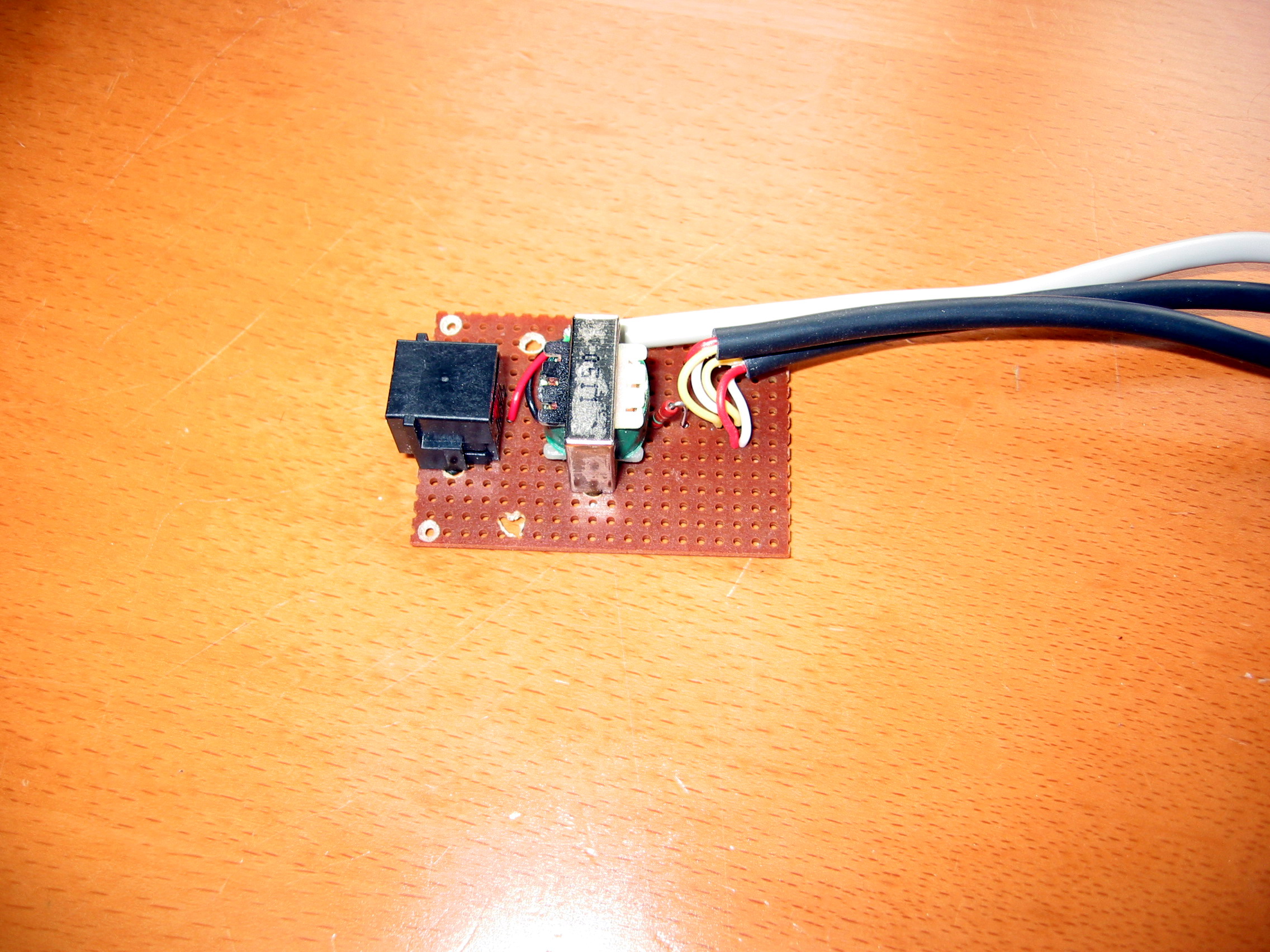
In a telephone system both the mic and the speaker signal are multiplexed into one signal. To be able to connect your phone to you mic-in and line-out of your pc you have to de-multiplex these signals. The solution of Chris was to extract the mic an speaker signal before it is multiplexed inside the phone. But this can also be done by a transformer (which is also used to prevent the 9V DC from going into you soundcard). The kind of transformer used for this application is a so called secondary centre tapped transformer. Meaning that it has 2 connections at its primary side (where the telephone will be connected) and 3 connections at its secondary side. The middle connection is physically connected to the middle of the secondary coil of the transformer. This middle connector is used as a shared ground for both the mic and the line-out.  Another issue is the input impedance of a phone line. When a phone line doesn├óŌé¼Ōäót see the right input impedance reflections will occur, resulting in echoes or even in disabling the line. A telephone line has a input impedance of 600 Ohms, so the transformer has to be a 600 Ohm transformer. At the secondary side of the transformer a 150 Ohm resistor has to be placed at the middle connection to make the secondary input impedance 600 Ohm as well, resulting in a balanced transformer. This all might seem complicated but as can be seen from this figure, the circuit is pretty simple and small. |
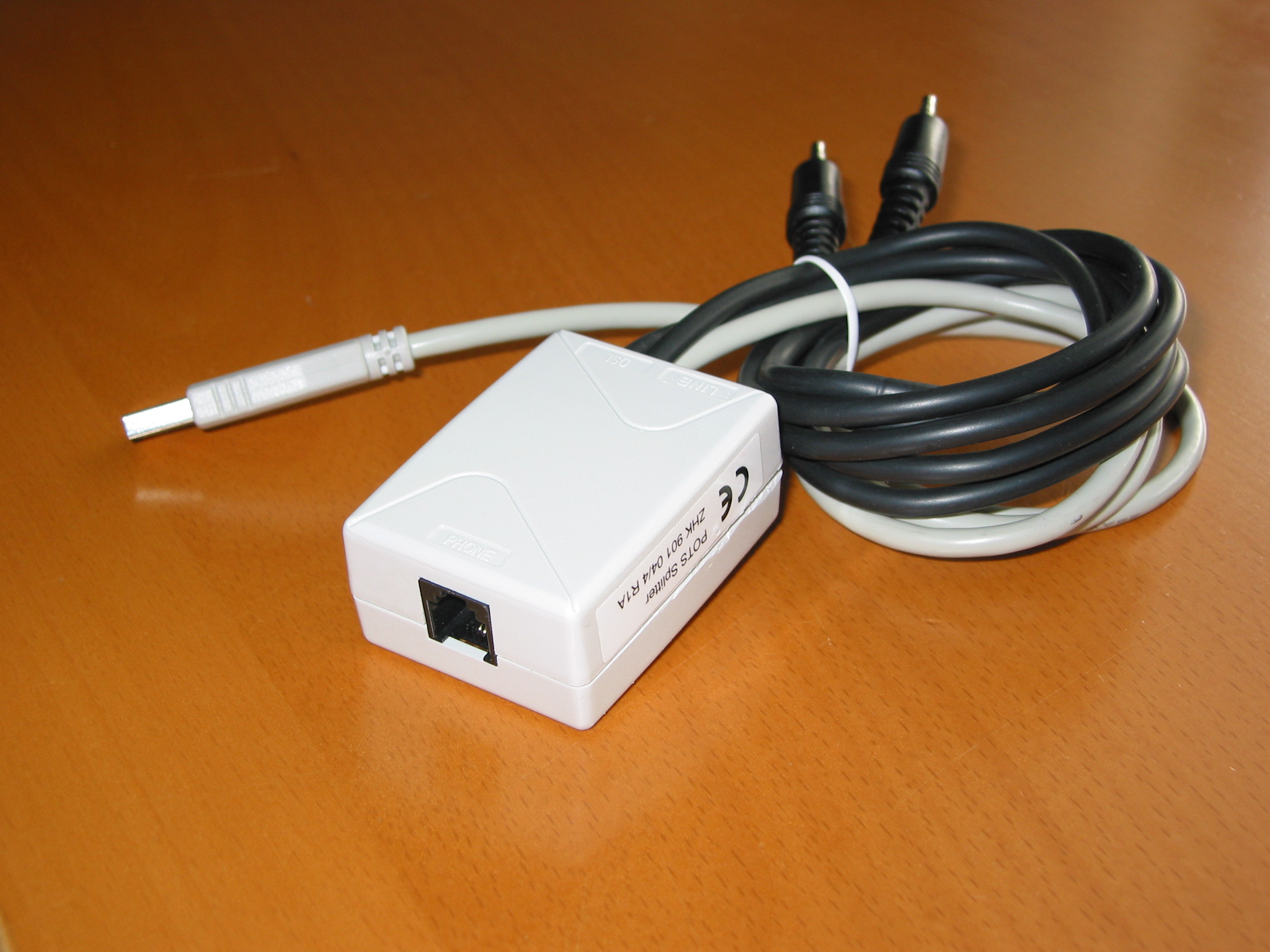
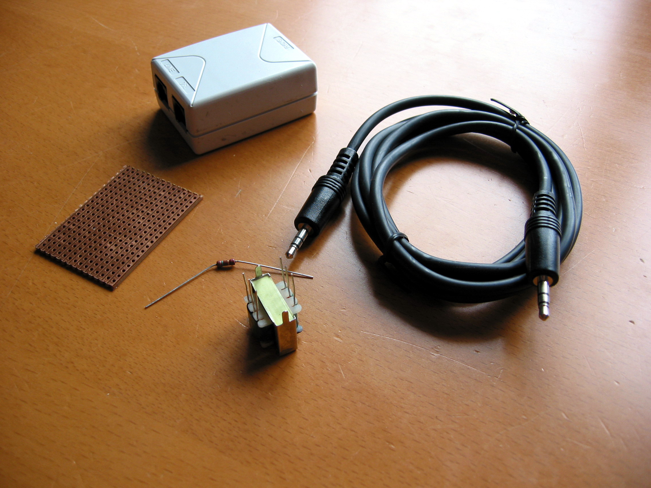
 For the connection to the pc jack-plugs have to be used, usually these are For the connection to the pc jack-plugs have to be used, usually these arestereo. For the microphone connector the left and right signal can be simply connected to each other at the circuit connection, so actually you make it a mono signal. For the speaker connection one of the left or the right signal should not be connected because your soundcard stereo output would be shortcut otherwise. (In most scenarios this won’t matter though as the sound from both channels are the same.) One funny thing is that it doesn’t matter which connector you plug into mic or headphones. The result will be the same as we have the transformer in-between the two cables. For the telephone connector a RJ11 female connector should be used, so you can attach any phone to your device. Everything can then later be put into a nice little box, and -hey!- let’s use a ADSL splitter. It will provide us not only with the RJ11 that we need but also a neat little box. |
On the next page we’ll have a look at the step-by-step building instructions.
rapidbox skype adaptor voip voice over ip,Go wireless with Olympia Cordless DUALphone, CyberPhone,skype usb phone rj11 adapter, cordless dualphone, FWD, Skype, Xten, Yahoo, Stanaphone, TerraCall pc mac laptop,VoIPBuster,Free conferance call,Internet telephony with Skype, Skype, , chatcord, VoIP,Voice over IP, save, new,cordless, Free phone calls, chat-cord, IP Phone, Skype compatible, free voip, dualphone, VoIPBuster
You must be logged in to post a comment.
Help us continue our work with a donation
 Forum {beta} Forum {beta}Hatch ideas and help others with their ideas. |


20 queries. 0.205 seconds


June 30th, 2005 at 6:59
hey this sounds like a really good idea and all but is it possible that you guys can publish a little more straightforward guide with steps and pictures for each step. because i have no idea how to do what is listed above, and i want to learn.
June 30th, 2005 at 8:47
Thanks for this description! Almost sounds too easy to be true
Maybe it’s a good idea to tell us the part number for the transformer or where you got it from?
I have been looking on the http://www.conrad.nl site, but I am not sure if they have the right tranny or which one I should get.
@dimo: there’s not much to tell is there? Only thing that isn’t clear is what’s + or – on the 9v battey or phone connection,
but I guess that’s very easy to find out; only 2 possibilities
Thanks again
Franc.
June 30th, 2005 at 8:55
a telephone line is symmetrical, meanding that the polarity is not an issue, meaning that you don’t have to worry about your + and – of the battery.
June 30th, 2005 at 8:56
Oh, one suggestion for the speakerjacks: I’d say, on both jacks, connect the tip only and not the ‘ring’. This way it really doesn’t matter where you
put microphone or speaker.
Franc.
June 30th, 2005 at 8:58
As mentioned in the text, the transformer isn’t easy to find. But the Bourns lm-np 1002 of 1004 will do the trick…
June 30th, 2005 at 10:56
dimo: I’ve added a step-by-step instruction to the article. Hope you like it ¤śē
June 30th, 2005 at 17:26
any plans for a usb version??? like one that uses usb opposed to jack-plugs for input/output? like a normal usb phone?
June 30th, 2005 at 17:51
Jax: Not really. But THAT would be nice.
The problem then is that you would need several active components as well as drivers for it. Basically POTS to Analog audio + Audio to Digital audio + USB controller. It would not be ‘economically feasible’.
You could of course use an USB audio card and then add the converter on this page to it.
June 30th, 2005 at 18:16
I’ve built this circuit – it’s documented here: http://www.tkk.fi/Misc/Electronics/circuits/teleinterface.html#simplehybrid
If you’re going to use the battery, don’t forget you need a transformer that can sustain 15mA or more of DC current. From digikey, lowest price first:
Tamura TTC-105-1
Triad TY-145P
Triad TY-401P
Tamura TTC-109N-1
Note also that SOME phones, especially cordless ones that have their own power supply, will work fine WITHOUT the 9V battery.
June 30th, 2005 at 18:35
It’s just the classic phreak box “The Rock Box” or a Rat Shack phone recorder, but it’s the idea that counts. Great idea!
June 30th, 2005 at 22:09
I’m having a hard time finding the transformer in the Netherlands. Anywhere I can salvage this from? An old modem perhaps??
June 30th, 2005 at 22:30
Build your own Chat-Cord
Voice over IP is taking over the world and I also like the idea of calling for free… The problem I’ve experienced so far is the fact that you always have to use those cumbersome headsets. When it would be possible to use your standard phon…
July 1st, 2005 at 1:47
Dude is it possible to make a more organised tut because this is really hard to follow?
July 1st, 2005 at 3:18
here’s a link to a transformer. not sure if they do international shipping. http://www.mouser.com/index.cfm?&handler=data.listcategory&D=553-TY304P&terms=553-TY304P&Ntt=*553TY304P*&N=0&crc=true
July 1st, 2005 at 12:15
I’d be interested if conrad.com has the transformer? Or has anyone else had any luck finding it somewhere in Germany.
Thanks
July 1st, 2005 at 14:56
Build your own Chat-cord
Jeroen over Grynx has done a very good DIY on building your device to connect your normal phone to PC. There is a similar device on the market called Chat-Cord but it is quite expensive – so why not make your own:
Not too long ago I ran across a …
July 1st, 2005 at 17:10
This is a great Idea, just What I’e been looking for for a while. I’ve been looking in an old modem for a transformer, but will it be the rtight kind of thing? Also, how do you tell if it is centre tapped or not?
July 1st, 2005 at 19:18
Good job. i just had a question. would these be the required parts i would need:
http://www.mouser.com/index.cfm?handler=displayproduct&lstdispproductid=281088
http://www.mouser.com/index.cfm?handler=displayproduct&lstdispproductid=340724
http://www.mouser.com/index.cfm?handler=displayproduct&lstdispproductid=428353
http://www.mouser.com/index.cfm?handler=displayproduct&lstdispproductid=341609
July 1st, 2005 at 23:15
I got up with a small idea to make the phone USB.
There are very small USB Sound blasters for sale,
on ebay you can get them as cheap as 6 euro!
In combination with the Chatcord you have the advantage that
you can also play your MP3`s and Skype all the way.
Altough you must be able to chose a Soundblaster for both actions.
http://www.usbgear.com/usb-audio-adapter/usb_audio_blaster.html
July 1st, 2005 at 23:19
Oh forgot to say that with the shipping costs of ebay it will ofcourse
be a bit more expensive, but cheaper than a converter or other phone….
July 2nd, 2005 at 0:46
Actually a few weeks ago I was thinking about something a bit different. How about writing a Skype to SIP gateway. That’s because of an offer of 1und1.de of a calling ‘flatrate’ for around 10/month to any landline in Germany.
If I had such a gateway, I would offer people free calls to numbers in Germany, maybe asking them for a small donation if they use it a lot, so I can cover my expenses.
However, I didn’t find any OS or free (as in beer) configurable SIP client to connect this to… I’ve lookep a bit into the Skype API, and it seems connecting to Skype should work (one problem being that Skype needs to connect to a soundcard, so I would also need a ‘virtual’ soundcard, if I don’t want to connect two soundcards together) or connect the phone line to the soundcard (my modem/router handles the SIP translation). Also this probably wouldn’t work directly with the device presented here as it tries to emulate the side of the phone-company. I’d have to emulate the phone.
What do you think of this idea, would you place a call through a Skype-VOIP-PSTN gateway (privacy implications…)?
Maybe you know of a solution already?
Kind Regards, Florian
July 2nd, 2005 at 17:31
Hmmmmmm, now if it only supported pulse dialing so that I could make Skype calls with my rotary phone……..
July 2nd, 2005 at 20:17
Poor Man VoIP
… que soluciona el problema utilizando un telefono casero. Los detalles los encuentras en la p├ā┬Īgina de Grynx
July 4th, 2005 at 7:47
One other thing you may want to think about – there are any number of USB sound dongles around, then you can put the skype audio through the USB device and keep the PC speakers for other sounds. You would stick the USB dongle into the box with the 600/600CT transformer, and the whole thing would be pretty neat and tidy.
I think that has a future?
July 4th, 2005 at 12:32
Hi. i have a question. i would be glad if anyone help me.
I have a cordless phone and the phone has its own power supply, so i don’t need to use the battery or use the usb cable?
in other words..(having a cordless phone that has its own power supplu i don’t need to do the step 5(Connect the + from your battery (or USB cable) to pin 6 of the transformer) and the step 6 (Connect the – from the battery to pin 3 of the RJ11 plug.)???
Thanks!!!!
July 4th, 2005 at 13:09
Bruno: I can’t tell for sure, I think it depends on your phone. I have tried a Philips and a Siemens DECT cordless phone which both do need the supply voltage. But, there are other people who have cordless phones that do not need the 5 of 9 volt supply… So what I suggest is that you just try if it works without, and if it does not, include the USB/battery power supply.
July 4th, 2005 at 16:43
hmmm.
how universal is ths telephone interface?
should this circuit work on telephone networks around
the world or is it based on some north-american specific telephone standard?
basically, am I going to get an angry
call from my provider? well, probably not a call
on my landline…
July 4th, 2005 at 16:59
dirk: this is universal…
But you might understand it wrong, this device is placed between your pc and your phone, it is not connected to your telephone line at all… So it is off course not illegal or something and your telco won’t notice you using it.
July 4th, 2005 at 17:43
it’s compatible with mac ????
July 4th, 2005 at 20:22
diego: Yupp! As long as you have sound in and out. Duh!
July 4th, 2005 at 20:39
Out of curiosity, should this thing work in the United States as well? The reason that I ask is I’m pretty sure the phone systems in Europe may be different (in terms of voltage, etc), and that could affect this thing… Has anyone had any success getting it to work in the US?
July 4th, 2005 at 20:59
D’oh, just read post 28 and realized my question was redundant… Whoops
July 4th, 2005 at 22:57
how about the Echo? is there any? thanks!
July 4th, 2005 at 23:14
Bruno: As long as you turn off the 20dB microphone boost in the volume controls no echoes due to the “chat-cord” will occur. What does happen is that you hear yourself talking DIRECTLY in your phone’s speaker. But this occurs in normal telephony as well (even if you might not realise it, just listen carefully ¤śē ) and is inherent to the way telephone-lines are built. Because this happens directly it is not annoying.
July 5th, 2005 at 8:05
Is there any way to make your own isolated transformer?? maybe if anybody tell us the awg and others details form the transformer, or tell us from where can we take this issue from old cards or devices
July 5th, 2005 at 12:59
Oh wow! This is such a great idea, the guy that invented this (Mr.Blond)is such a genius!
I hope that he calls his girlfriend every night, just to enjoy his chat-cord. Congrats and good luck to you all builiding it!
July 5th, 2005 at 16:23
Build your own Chat-Cord
Build your own Chat-Cord…
July 5th, 2005 at 18:44
Awesome! I can’t wait to try this.
July 5th, 2005 at 19:50
Nice and simple… I’ve got a Logitech usb headset that’s going to be modified a bit
Maybe this could be expanded with a PIC/other microcontroller to allow selecting skype / POTS from the phone – THAT would rule
July 5th, 2005 at 20:09
If a cheap voice modem can function as an IVR (Interactive Voice Respond) or Answering machine, why can’t we turn it into this Chat-cord device? Everything is already in this voice modem. The RJ11 jack, power, sound device. I am not a programer myself, but I am sure using Skype API and TAPI (Telephony API) can definitely do the job. I wonder if I can start my own company for this idea. Heheh Well, not that I mentioned on internet, someone else will do it. Not being a show off, but 8 yrs ago when I first used “IP Phone” (Yes, a software company called IP Phone), I already thought about bridging VoIP to PSTN because I live in America and many relatives are over sea. But at that time, I was using analog 14.4k modem and don’t have 2 land lines, anyway, don’t mean to go tangent.
With this combination (Voice modem, Skype API, TAPI), we can bridge VoIP to PSTN. Basically function as an ATA. I read voip-info.org once in a while. But the people there are guru. If no one think of this idea, I am sure there are some issues implementing this. Is it because voice modem has only one sound device so it cannot work in full duplex? Or is it because people at voip-info are perfectionist and they don’t want to use voice modem because it cannot be fully compliant as a FXO? For home user, we don’t really need to make our PC to be 100% FXO. We just need to be able to record and playback wav to the PSTN line. We don’t care about timing, etc. The voice modem can detect all that (valid dialtone, busy signal, fast busy, etc) for us.
So is there any guru here can explain why can’t we make a voice modem to bridge Skype and PSTN?
July 5th, 2005 at 20:39
In response to post number 31. European and US phones use the same voltages. I’ve used phones (and modems/fax machines) purchased in the USA in Europe without any problems.
July 5th, 2005 at 21:57
I have an idea for a USB version. I haven’t tried it, but maybe someone here can comment on the feasibility.
Could the wires from an inexpensive USB headset with microphone be used to build a USB-only version?
July 5th, 2005 at 22:08
How about using a modem to do this? Does anyone know how? Could you simply supply 9V to the phone line and hookup the phone directly to the modem? Seems like it would require less hardware and be easier to interface with telephony apps?
July 5th, 2005 at 23:03
Let’s say I decide to disconnect my home’s internal phone wiring at the demarcation point. If I plug this DIY device into a wall jack — allowing all the phones in the house to access the VOIP service — is there a guide on how much more power I should budget for?
July 6th, 2005 at 0:11
Robocoder, if you do not have service from a telco, you would assume it is not connected to the CO. However, technician sometimes make mistake or they don’t bother to really disconnect all the wires. If somehow the CO ring your line, it’s going to send you the ring voltage. If you equipements are not properly protected, it will fry them.
July 6th, 2005 at 0:47
I’ve found everything on Digikey except the “Print Board”. I’ve wanted to use print board in project before, but have never been able to find them. I’ve also heard them called by different names before (I forget which, off hand.) Anyone know anyplace I can get these? These are way handier than doing chemical etch circuit boards, but still more perminant than breadboards (plus I’m sure they’re cheaper than chemically etching, and I won’t have access to the school forever)
I live in the states. Thanks!
July 6th, 2005 at 0:50
The chat cord is listed at $23.99. Not that expensive.
July 6th, 2005 at 0:51
Hey! They call them “Prototyping Boards” I guess. Find a bunch on Froogle over here:
http://froogle.google.com/froogle?svnum=10&hl=en&hs=hBG&lr=&client=firefox-a&rls=org.mozilla%3Aen-US%3Aofficial&tab=if&scoring=p&q=prototyping+board&btnG=Search+Froogle
July 6th, 2005 at 1:24
You’re right, if it’s only 25 bucks you’ll be hard pressed to build a cheaper one… but what if the parts were free?
Observe: every cordless phone and answering machine already has this circuit. If you have a broken or useless instance of one of these devices, take it apart, use the parts, or just solder plugs to the audio taps on the board.
July 6th, 2005 at 2:09
Hi, i have another question, i don’t have here is my house the battery and the usb cable.
will the device(chat-cord) work if the baterry or the usb cable isn’t installed?
i’m sorry if my question is stupid, but i still don’t understand the purpose of the battery
thanks!”
July 6th, 2005 at 3:17
If you already have a soft modem…
I have an AC’97 AMR modem as part of my laptop. In Linux it shows up as a second sound card with no proprietary driver required; it is capable of recording and playing back audio at a phenomenal eight kilohertz! (That’s what the phone company uses to transmit normal phone calls. No good for higher quality voice recording though, which might be fun to do with a good telephone headset and a chat cable.)
Trick 1: a normal phone cable plugged from the wall to the laptop lets me record whatever’s happening on the phone line into the laptop. It seems like it’s always off the hook oh well. Maybe I’ll do this if I get a podcast and want people to call my land line.
Trick 2: With some skill you too can construct the SuperTellyUltraCable to connect your phone directly to the voice modem. Warning: no warranty. May break your phone or modem. The SuperTellyUltraCable is a normal phone cable. Two wires connect the phone to the laptop. Wire a nine volt battery in series with one of these two wires. Now you too can speak and play back with your telephone headset.
July 6th, 2005 at 3:42
Bruno, RTFA. Particularly this part:
First of all the normal telephone line has a certain voltage, depending on the state of the line….. So to be able to use a normal phone to make it think a call is going on, the phone has to see a 9V DC voltage at its input. This can simply be achieved with a 9V battery.
July 6th, 2005 at 3:53
Hey guys. To detect a ring in skype, a simple LC circuit could be used.
(http://en.wikipedia.org/wiki/RLC_circuit will interest you)
Here are the steps you would use.
1. Create a ‘ringtone’, i.e. wave/mp3 file in an audio studio type app
(maybe Audacity, its free and it’ll do it)
at a specific frequency, maybe 18khz. Or, you could grab your favourite
ring tone, and mux a tone over the top of it at barely audible levels
(audacity will do this too). Using a high frequency like 18khz means you
wont be able to hear it.
2. Build a circuit. What we need this circuit to do is filter all frequencies
bar our specific frequency, then use this frequncy to trip the circuit to
pump out 100vac to the phone, hence, making it ring.
To determine what components will be needed to
detect a specific frequency use the equation listed on the above mentioned
wikipedia page… An inductance value of 0.00008H and a capacitance
value of 0.000001F will give you a resonant frequency of 17794.06 (17.8khz).
This is basically a notch filter setup, but we will be using it to filter
out everything BUT the frequency the notch is setup for.
Using an Op amp, a resitor, a capacitor and a potentiometer, you can
then use the OP amp output to trigger the ring circuit… Anyone want
me to invest more time in explaining? Or will it be wasted?
July 6th, 2005 at 4:34
What I would like to see is a “converter” from telephone cord to USB. Where the device both is powered by USB and sends the signals to the telephone (something like an iMic, but with a phone jack.)
July 6th, 2005 at 4:43
I think they are called “USB modems”….
July 6th, 2005 at 4:47
my last question before buying the battery…. i will use this device(chat-cord) with and old telephone, it is a corded telephone
so i do need to buy the battery or don’t? (i don’t plan to do the usb version of the device(chat-cord)
thanks for help!!!!
July 6th, 2005 at 8:35
Yes. Yes bruno. Without any power source your phone will NOT work. The phone needs a voltage in the phone line in order operate and will not work if there’s no power. That power comes from either a) the battery or b) the USB. You NEED ONE OR THE OTHER. The only time you might luck out is if you have a telephone that plugs into the electric outlet already, but that is only a sometimes thing. Just assume you will need either the USB or a 9V battery.
July 6th, 2005 at 8:36
sorry guys… now i understand… the battery is necessary..
now i will start building the chat-cord…….
thanks!!!
July 6th, 2005 at 8:50
XCol:
Wouldn’t you need a 100v power source connected to the op-amp in order to get 100v output? I understand the bandpass filter, but I don’t quite understand how to hook up the op-amp to burst the 100v when I only have a 5v (or 9v w/ battery) power source available. Isn’t the op amp gain limited by the supply voltage on the +/- Vcc pins?
July 6th, 2005 at 9:03
Good thinking, XCol!! I understand your idea, and I haven’t thought of it that way. But it is actually a nice way to do it in hardware. I am only wondering of how to create the 100VAC… Maybe another transformer or something. Explaining something more sure isn’t a waste of time!!
p.s. if you prefer private conversation mail me at mr_blond18@hotmail.com
July 6th, 2005 at 9:31
XCol: I like your idea, couldn’t you use that “frequency trapping” circuit to trigger the phone’s internal ringing circuit (ie. figure out how to bypass the circuit that intercepts the ~100VAC and trigger whatever it triggered?).
I hope I explained that well enough, the lack of sleep is starting to get to me ¤śĆ .
July 6th, 2005 at 9:38
heh … nevermind, I thought this was http://www.grynx.com/index.php/projects/siemens-skype/
July 6th, 2005 at 10:56
Hi:
I was wondering how I can use this with an iBook. An iBook does not have a in jack or a Mic jack.
I am based in australia. has anybody tried it on telstra..
Suhit
July 6th, 2005 at 16:36
So is this the “rat Shack” box that will work?
If so, how do I hook the thing up? I already own a few of those.
July 6th, 2005 at 21:17
Radioshack Part #’s
2760148 – Dual PC Board – $1.79
2790355 – Telephone connector box – $3.99
4202434 – Mono audio cable – $3.29
2711109 – 5-pack 150 ohm resistors – $0.99
2731380 – Audio transformer – $2.99
And if you want that timer chip,
2761718 – TLC555 TIMER – $1.69
I haven’t decided what transitor and powersource yet, though. I’ll get it working first.
Yes, Radioshack is somewhat expensive.
July 6th, 2005 at 22:29
syberdave, the audio transformer you mentioned is a 1,000 ohm primary tapped, 8ohm secondary.
Since the circuit is needing a 600ohm on both primary and secondary I dont think this will do the trick.
You are welcome to try but 8ohm seems a little low when it should have 600ohm on the phone side of the circuit.
I would stick with http://www.mouser.com/index.cfm?handler=displayproduct&lstdispproductid=281088 as mentioned above in 18.
Also If anyone can find any old modems with an Atech ATS-127A transformer on it..
The specs on that are perfect for this project and actually have a better frequency response than the part at mouser.
I found one on my creative modem blaster 56k.
July 6th, 2005 at 23:03
In case ya’ll haven’t realized, the mic plug on pc’s is powered on the ring contact; this being said, I am not sure as to the exact voltage (18V I think), but with the proper resistor u could power the device with out the need for USB.
July 6th, 2005 at 23:33
OK, upon further research (and trying a voltmeter), the actual voltage is more like 3-9V depending on the PC. If your lucky you can still power the device in this manner.
July 7th, 2005 at 0:31
Soulhuntre-
No, the device you mentioned is just a recorder. That will let you hear what’s on the phone line. If you wanted to use that device to plug a phone into your computer you would have to add some voltage between the rat shack and the phone. (a 9v in series should work)
The rat shack will NOT let you plug from the speaker out on your computer to the telephone, though. You would be able to use your telephone as a microphone, but you would still need a pair of head phones to hear the computer. (There are two plugs on the “rat Shack”. One plugs into the microphone port, the other plugs into a CONTROL port to tell the recorder when to start taping. Not the same thing at all, really, and way more expensive.)
July 7th, 2005 at 0:36
Syberdave-
What’s the FlipFlop used for then?
July 7th, 2005 at 5:38
Okay guys, gettting 45vac (you really dont need 100vac, 45 will do nicely)
from a 5v circuit is a little more difficult.
That said, it is deffinatly not possible. There are 2 relativly easy ways to
do it. Way #1. Use a 555 timer, and an OP amp to genertate a 2vac
signal at 50 hz. (i say 2 volts because the opamp wont swing the whole 2.5v,
and ac is measured ground to peak, not peak to peak.)
Then use a 1:35-60 (anything in the 40-150vac range will make the phone ring)
transformer to step the voltage up. We need about 30ma, this setup should
be able to crank that out.
Way #2 Get onto an electronics site and find a small kit that will
invert 12vdc into 250 or 120 vac, then feed it 5vdc. Easy, providing
you dont fry your brain before hand.
Once you have decided your path its just a matter of making the ring
detection circuit trigger the ring voltage circuit. hell, here is an idea,
do this with a transitor/low voltage fet/op amp in the RLC loop
previously described (connect the gate or base of the device to the RLC
circuit, the collector to the + rail, and the emitter to the ring voltage
circuit… use a 100uf capacitor between the emitter and ground to flatten
out/filter the 18khz signal that is trigering the fet/transistor.
wanna chat some more about it? col_col83 at hotmail.com
July 7th, 2005 at 10:31
online gambling
Take your time to check out the pages in the field of blackjack online casinos
July 7th, 2005 at 17:43
Is this possible with a transformer which has no center taps? I’ve got a bunch of modems but none of the T’s are center tapped, what would the changes be?
July 7th, 2005 at 17:53
As read in the article, the flip-flop could be used to generate the 100V AC at something Hz that you need for the ringer. (As XCol said above.)
I put my thing together and it works perfectly. Would it work even better if I got the right transformer?
Oh, I’m looking at my old modems (I have 2) and I think that I could take the transformer from them. That seems like a good idea, since I want to make another one so I could make a virtual PBX and have it connect to an outside line. (I have 2 sound cards.)
July 8th, 2005 at 0:26
Just a quick note for anyone following my radioshack part numbers. I bought the wrong mono audio cord. Mine only has one side, so I ended up taking another plug from an old microphone.
You’d want to get a double-ended one as shown in the picture in the article.
July 8th, 2005 at 0:35
Phil, you need one with center taps if you want to use both recording and playback at the same time. Otherwise, you could only have one. Half duplex vs. Full duplex.
And XCol, I think that there are features in the Skype API that let your computer know when it’s ringing. If the computer knows, you could use the Serial port to control a relay to start the ringing? Like if you would go through the trouble of making that detector circuit, you could probably make the serial-port thing easier providing you know how to program.
July 8th, 2005 at 2:10
The Radio Shack stereo cord:
4202387 – 6′ 1/8″ Stereo to 1/8″ Stereo Cord – $4.99
July 8th, 2005 at 7:17
Mr Blond,
Need a clarification:
[Quote]
5. Connect the + from your battery (or USB cable) to pin 6 of the transformer.
6. Connect the – from the battery to pin 3 of the RJ11 plug.
(USB) Red is +5v and black is ground
But from the image you attached (http://www2.jarnaker.com/wp/projects/chat-cord/IMG_4342.JPG), it seems that RED (+) is connected to the RJ11 and BLACK (-) is connected to the transformer instead.
Which is correct?
Thanks.
July 8th, 2005 at 7:22
# Nathan Says:
July 1st, 2005 at 19:18
Good job. i just had a question. would these be the required parts i would need:
http://www.mouser.com/index.cfm?handler=displayproduct&lstdispproductid=281088
http://www.mouser.com/index.cfm?handler=displayproduct&lstdispproductid=340724
http://www.mouser.com/index.cfm?handler=displayproduct&lstdispproductid=428353
http://www.mouser.com/index.cfm?handler=displayproduct&lstdispproductid=341609
hey the resistors you named in one of those links are not the right ones, just got them in the mail today, they are huge!, they are the 10w and there suppose to 1/2w, you can get atradio shack
July 8th, 2005 at 8:58
Patrick: You’re right. In the picture the polarity of the USB-voltage in inversed. But as said in post nr.3 the polarity doesn’t mather, this will work in both ways.
Just for simplicity it is said that the + should be connected to the transformer, otherwhise everybody would be asking the same question as you did ¤śē
July 8th, 2005 at 10:08
Mr Blond: Great! Thanks for the prompt clarification..this would be my weekend hobby project
July 8th, 2005 at 18:11
Had no luck in find a 600:600 centre tapped transformer locally. They did have a 500:500, 8Ohm center tapped. Any thoughts on making that work? Having said that, I happened to have 2 600:600 non center tapped transformers from another unfinished project and constructed one use seperate transformers for each input and it appears to function properly as well.
July 8th, 2005 at 18:22
syberdave: Glad the parts worked for you, I might run to radio shack at lunch and get that transformer to try it out.
As long as both parties can hear each other, I think it would be just down to thee issue of frequency response.
Phones arent that great to start with but, the better frequency response you have, I would think the better everything would sound it would be. How is your sound quality compared to a regular phone or compared to skype with speakers/microphone?
The 600:600 transformer might come into play more with other phones that may be more picky, but who knows it may work just fine. ::shrug::
Not only do we need to implement ringing somehow, but on-hook/off-hook detection as well to hangup or pickup the call.
July 9th, 2005 at 1:02
Hey XCol, could we skip the 555 circuit and just use the ringtone
to generate a 50hz signal? That could be a 50hz-pulsed 18khz sound fed
right to the transformer from the notch filter. Maybe we’d still need an
op-amp but heck, I could live with that.
July 9th, 2005 at 17:20
confusedpc: how did you get two 600:600 transformer non-ct to work?
syberdave: the part you had is a 600 ohm to 8 ohm is it not? they have a #273-1374 which is a 1:1 but i need to know how confusedpc got his to work above
July 9th, 2005 at 17:29
i got mine semi working but there is a lot of crosstalk between them. my litmus test is that if i play a mp3 i should not pick up anything through the windows sound recorder. otherwise people will hear their own echo, so i’m curious how you got it to work with 2 600:600 non-ct.
July 9th, 2005 at 18:17
Mr Blond:
Got the parts & fixed up but hear a “drool” tone on my phone (even w/o connecting the mic/speaker to my laptop). After connecting everything up, there is 1 wire each from the mic & speaker which is not connected to anything. Is this correct? The ground of the mic/speaker are connected to the resistor which is connected to pin 2 of the transformer. The “other” wire of the mic/speaker is connected to 1 & 3 of the transformer. I’m using the USB cable to provide power and a 1/4 watt 150 ohm resistor. Any help is appreciated. Thanks!
July 9th, 2005 at 18:40
i really like to chat with people on line
July 9th, 2005 at 23:11
confusedpc:
Compared to phone and skype, it sounds fine. I have it connected to a cordless phone with a hands-free thing and I even listen to music on it. But when I used Skype, my mom complained that the sound quality was bad. But maybe that’s because it’s connected to someone in Taiwan and there may be latency.
I’m in the process of building a device that sends a ring signal, with the help of XCol’s instructions. I’ll publish a step-by-step howto with pictures when I get it done. (If it works, that is.)
I don’t expect to need on-hook/off-hook detection, as I plan to make a pickup/hangup controller. I’ll have a serial port thing that controls a relay that sets the phone line connected or disconnected.
And for the ring detection, I plan on just making my modem do that. It can detect rings, and as a bonus, it can read Caller ID.
I know that my hacks are dirty – 2 sound cards, 2 chat cord things, a ring sender, and my modem. And on the software side, I have a script that reads DTMF tones and responds accordingly, and I’ll have to write a Python script that controls Skype API so it can dial and stuff.
I use Linux, btw.
July 9th, 2005 at 23:18
The ring sender thing is coming out to be expensive. I’ve spent around $30 on it, including a pack of 500 resistors (which could last me years) and 2 relays (damn, these are expensive; but I need them to switch the phone circuit to the 100v line; damn, I bought a SPDT relay and I need a DPDT. Damn damn damn.) But it’s about $20 without that big pack of resistors.
I couldn’t find a 1:50 transformer like XCol said, but I found a 120VAC to 6VDC wall transformer and 1:20 should be enough, since I read that about 50VAC should be enough. It’s so hard to open the stupid plastic case without a saw. At least I had a power screwdriver.
July 9th, 2005 at 23:21
ehwhat:
I think I’m getting crosstalk, too. It’s really annoying. When I’m playing a MP3, the data gets sent back to the record slot and the DTMF reader sometimes picks up weird signals. If anyone finds out a way to get rid of it, It’d be great.
July 10th, 2005 at 7:47
Followup: 1k to 8 ohm transformer
I’ve had crosstalk problems (me playing a MP3 will feed garbage to the DTMF decoder) and I’ve always thought that it was my sound card’s fault – until I messed with every setting to no avail.
So yeah, I’m having CT problems just like #86. I feel stupid now. Sorry for suggesting the wrong thing.
But I did buy a 1:1 non-CT transformer. How do you do full duplex with it?
July 10th, 2005 at 20:44
Well, friday while at work i build the cord using syberdaves components(the radio shack transformer).
I borrowed headphones to use on my pc, and my coworker had the phone at his pc.
When he spoke it sounded fine. I didnt have a mic at my end so we were not able to test it the other way.
He called a friend on the phone and there were some problems with us hearing him and he mentioned an echo or someting..
waiting ont he 600:600 transformer to come in to build it with those parts, more later.
July 10th, 2005 at 21:43
By the way.
The modem that has the Atech ATS-127A transformer on it was an ISA card.
Wanted to mention it because the part has great frequency response.
The low end of the frequency range is lower than the 300hz on the other transformers…
May not matter much, except for those those wanting absolute best.
July 11th, 2005 at 12:49
Hi guys. I m really loving wat u are doing to help us with free calls.
can any of you give me step by step of how to make that chat-cord.
I have tried hard but i still can’t manage to do it.
What should it buy? from where? how to cellect them?
Please make it simple….
Take care guys!!! jeje UK
July 11th, 2005 at 13:09
hey!!! where are you guys. I can see that most of you got it already.
I wish you could direct me how to have fun with free calls.
I am stupid in electronics.
Come on tell me what 2 do step by step.
what to buy (technical names),how to set the up and so on.
Oh God…i m just crying of being to far behind!!!!
July 11th, 2005 at 13:11
Would this be a correct transformer to use?
http://www.eijlander.nl/article.php?group=899&id=203478
I’m not realy into EL, so I’m asking just to be sure :).
July 11th, 2005 at 13:15
Non-El: That is the one to get. Actually I think it is the same one as used in the pictures of this article…
July 11th, 2005 at 13:32
jupiter:
1) Buy the parts mentioned above.
2) Follow the instructions.
3) Plug it in.
and you could only make free calls to people over Skype. SkypeOut (PSTN) costs money.
July 11th, 2005 at 16:15
Any updates on the ring circuit?
Part numbers, diagrams, etc.
So far we need some resistors, an op amp, a 555 timer, and a potentiometer
This where Im starting to get a little lost. That wikipedia page is way to much for me.
July 11th, 2005 at 17:32
For the ringer, XCol gave me the following circuit: http://syberdave.net/dv/circuit.gif .
That would give a 100VAC signal on serial cue. Then, we’d need a way to switch it into the phone line. I’m thinking about using a relay.
I’m going to hold off the ringer until I get the echo problem fixed.
July 11th, 2005 at 19:27
Is there anyone who can tell which transformer to buy and where in the Netherlands?
I’ve searched on conrad.nl, but could not find it. I’d really like to know!
July 11th, 2005 at 19:39
Thank you
A few questions:
1. In reference to Q1 and Q2: Transistors? If so what kind.
2. On the Serial line in: what pin on the serial port?
3. I would like to use the idea mentioned in post 53 by XCol using the “notch filter” instead of a serial trigger. I assume that the serial line in would connect to the filter circuit from the description in 71.
Thanks for the contributions XCol and syberdave, this thing is going to rock.
July 11th, 2005 at 20:41
Hey, I just bought this 600P / 600S CT Trans,
http://catalogue.e-sonic.com/cgi-dev/part?manucode=195&partnum=101F
But it’s got 4 leads on either side? What up with that?
July 11th, 2005 at 21:09
Find pin 1, it looks like it may be marked with a white line.
pins 1 2 and 3 are for one side of the transformer pin 4 looks like it is not used.
Opposite side, pin 5(opposite of 1)
looks like it is not used so the other side of the transformer is using 6 7 and 8.
Ignore 4 and 5 I think.
July 11th, 2005 at 21:12
Sorry it looks like 5 is opposite of 4 instead of 1.
Still ignore 4 and 5 though, just note the locations and the pin assignment on the page.
July 12th, 2005 at 3:27
confusedpc:
(1) “Now, select a transistor type to use… You need darlington NPN type, so 2 BC517’s, BC618’s, TIP100, BC182…. there is a huge range that will work here. Find some that suit your budget, neither will be putting out much heat, but you dont want to use tiny units either!”
(2) I’m not sure yet. I’m going to stick a LED in random places and run I/O code to see which one can control what.
Anyway, I haven’t contributed anything – everything came from XCol. It’s just that I asked.
July 12th, 2005 at 14:39
Thanks,
Ok well, you went after the info and are building one and posting results so.. it still counts in my book.
Anyways, Ill add one of those transistors to my cart after checking them out a bit.
July 12th, 2005 at 16:21
Worked like a charm, thanks for the tips all, this trans worked perf,
http://catalogue.e-sonic.com/cgi-dev/part?manucode=195&partnum=101F
http://www.e-sonic.com/
Although $18 CAN is pricey, it is cheaper than ordering a $5 USD trans from the US. Can I remove the battery and use this to feed audio from my pc out into normal telephone calls? or record calls?
July 12th, 2005 at 17:15
syberdave,
Thank you for above reply.
Did you mean that if i decide to go for PSTN (skypeout), i would be
able to to call anynumber in the entire world? Do you really mean that?
I would love to spend on it.
Please help if you can!
July 12th, 2005 at 20:02
jupiter: yes that’s true. It costs roughly 1.7 eurocent per minute for every landline across the world (at least in most western countries). But watch it, it isn’t possible to be called…
July 12th, 2005 at 21:22
Jupiter: Have a look at this site http://www.voipbuster.com
They offer FREE phonecalls from your computer to landlines in many countries. How they manage to do this for free is a question to me, but I signed up (costs ├óŌĆÜ┬¼1) and I’ve already called several friends in other countries for free.
July 13th, 2005 at 1:04
hey, great hack!
has anyone from the UK managed to source the relevent parts?
I can’t seem to find the transformer at Maplin?…
cheers for any advice
-roof
July 13th, 2005 at 2:41
jupiter: http://www.skype.com/products/skypeout/rates/all_rates.html ; there are the rates. It’s not too bad. I use it sometimes.
And yes, you _could_ get incoming calls with SkypeIN. IT’s like $10 for 3 months, which isn’t bad.
July 13th, 2005 at 17:37
Order online:
https://www.alliedelec.com/Cart/ProductDetail.asp?SKU=283-1120
https://www.alliedelec.com/Cart/ProductDetail.asp?SKU=863-0119
https://www.alliedelec.com/Cart/ProductDetail.asp?SKU=928-9020
I’ve got the other parts, or can grab from Radio Shack, otherwise these prices seem relatively good for anyone. Not sure on shipping yet.
July 19th, 2005 at 12:39
Well, here is the question again… Sorry for that..
Is this the right transformer?
There is also a datasheet on the page.
Thanx!
July 19th, 2005 at 15:02
Thanks for the link Carson, I ordered yesterday from allied electronics, shipping was only $6.36 (UPS Ground) to South Florida, USA. The only downside is that their website does not tell you the shipping cost when you checkout, it’s calculated afterwards and then sent to you via email. Seems like a good company, we keep everyone posted.
July 19th, 2005 at 22:05
So, I built this thing using thr bourns lm-np-1002 and I’m getting a god-awful hum on my phone. I’m using a wall-wart to supply the 9V instead of a battery. Also since i wanted to make sure it works it’s just jumpered together, not soldered. Any ideas on how to get rid of the hum?
July 19th, 2005 at 23:07
shitaka: Your problem is most probably the power source. Try to use a battery instead and see if it goes away.
A regular ac/dc adapter will only provide a somewhat clean current if you put it under a load, but that won’t work in this circuit.
July 20th, 2005 at 3:35
This can be used with voipbuster.com right?
July 20th, 2005 at 21:51
Hello,
Is it possible to use the same phone to skype and telephone line ?
July 21st, 2005 at 1:10
Hi,
Nice and simple circuit, tutorial is good enough (kinda like my hd44780 lcd hack http://nerdhero.org/index.php/Howtos/LcdDisplay ). And liked the idea on getting the ring signal with right frequency on the line out to electronically switch different circuit for ringing (post 53 Xcol).
Was thinking of different switch, mainly switching between landline (PSTN) or skype. Imagine you have your cordless phone hooked up, sometimes you want to use the landline (maybe when pc is switched off or your inet connection is gone or whatever) and other times you want skype.
Would it be possible for instance to make the key ‘#’ or #+some digit sequence on the phone trigger a switch.
This way I could do something like #1 12345 -> calls 12345 on skype and
#2 12345 -> calls 12345 on regular line.
Ofcourse meaning hooking this box up to phone line + pc. This is in essance the same kind of circuitry but then catching a sound frequency from the phone output instead of the line out.
Actually the switching idea kinda already exists and is for sale here : http://www.dualphone.net/ but I will have same problem getting it in my country and/or probably high price tag…
Ow yeah and some people ramble here on using a modem to do this instead of building the circuit. Don’t really get the point of it (like post 40). All a modem does is do analogue/digital transformations to send data over phone line. Don’t see how it’s gonna help you talk on skype. Only thing an old modem is good for is ripping out the 600/600 transformer :). Ah ok, sorry, he’s talking about a voice modem euhm nevermind this paragraph then hehe
Anyway, happy hacking … hope to see some of you at What The Hack 2005!
This is where we plan to get the homebrew chat-cord working under linux (so rewriting the software in linux to capture the phone key sounds from /dev/dsp will be fun ¤śē )
July 22nd, 2005 at 4:40
I have already finished the DIY chat-cord,works perfectly, excpet, people will hear they ECHO after 1 or 2 sec, I checked every single wired, No short at all, also I’m musing 600:600 Ohm Center Taped Transformer…
Anyone has this problem???? how do you solve it?
Thank you!
July 22nd, 2005 at 7:52
Alex: try turning down your volume. Make sure your microphone is muted in the playback part of the volume controls, but select it in the recording section. It will probably be crosstalk sent back to the other side.
July 22nd, 2005 at 8:39
Hi Mr Blond, I have try to miniaisze my voice & mic volume, also disalbe +20db and muted the playback part of volume control,
people can still hear the ECHO very clear (delay few seconds), i try to disable “center tape part” and attach the “center tape” make no difference, wondering any body else has same problem?
Thanks
July 22nd, 2005 at 9:27
you could configure skype to ring the pc speaker, in tools–> options, that way you dont have to depend on your sound card
July 23rd, 2005 at 5:05
Hi, this is an awesome write up. I have only a basic (very basic) understanding of how this works, and am working on soldering one together myself. After visiting radio shack and finding most of the parts as described, the transformer only has 4 leads, but is 1:1. Getting confused by it, I de-soldered a transformer off of an old pci asustek modem, which I think will do the trick, assuming (properly I hope) that this is the transformer, but it only has 5 leads on it. Any suggestions? The transformer is labeled LB-2943-CT Link Com 9911 . Google turned up nothing matching this string, so if anyone knows if this is right, it would be appreciated.
July 23rd, 2005 at 8:45
@Non-EL: That trannie found at eijlander.nl is the one to get (read mr. blond’s response). ).
).
I am about to order a few (shipping costs are a bit high
Let me know if you need one too, we might be able to work something out.
Franc.
July 23rd, 2005 at 16:02
@Franc: I’m not sure if I’m going to order it. I have two old modems that also contain 1:1 transformers (well contained actually ;). I think I give those a try first.
But thanks for giving me the opportunity!
(Still wondering if the conrad transformer with order#: 516686-8B is the right one (www.conrad.nl). They give a 10 euro discount now :p)
July 23rd, 2005 at 16:30
Nen-EL: The conrad transformer you mentioned is NOT the right one, it is not center tapped…
July 23rd, 2005 at 16:33
Rick: If your transformer has 5 leads use the side which has 3 wires as secondary side (to the pc) and the side with 2 wires as primary(to the phone). Actually you have found a transformer that is perfectly suited for this application, while I (and many other…) used one which was center tapped at both sides (6 leads), which is not necesarry…
July 23rd, 2005 at 18:14
Mmmm…. I thought about using something from an old modem too, but there’s nothing on there that seems to be center tapped.
Would any old phone have a tranny that could do the job??
July 23rd, 2005 at 19:51
mr.blond: Any idea on the pin configuration, at least in regards to the instructions? It’s a bit daunting, as looking at it, wit hthe two pins facing me, I beleive pin 1 to be at the bottom right corner, since there is a rather large bump there, which I would assume is supposed to be pin one. Anothr problem with it is, on the 3 pin side, the middle pin has a 3 embossed above it, which is making me really question which lead is which. My site is down currently so I can’t post a pic, but owuld be more than happy to share some photos of the modems I ripped this off of as well as of the transformer itself. cyberwormatgmail if you’d like to see and offer up some friendly advice. (to be shared on here once we know what’s up with this thingy)
cheers
July 24th, 2005 at 14:48
Mr blond
There is one thing i still not understand. we,ve been talking about
how to build a chart cord. What about buying it? Does it cost too much?
Will i only communicate over IP with only a chat cord OR i will need it
for skype out?
Suppose that i buy it or i manage to build it. willi still have to pay some
money for calls (PSTN).
Thanks.
July 26th, 2005 at 3:19
Hi just finished my chat cord.
Works perfectly in windows xp but I also had to turn volume down to get rid of echoes.
Also not all phones work, I tested 3 and 1 did not work.
Having that said, found all parts here in little belgium for about 9 euro at http://www.rato.be
Here are some pics of my version : http://walle.nerdhero.org/chatcord/ .
I also used an extra adsl splitter box as housing so mine looks surprisingly similar except had to resort to sticky tape to keep it together because did not have any glue lying around ;).
July 26th, 2005 at 9:53
@jupiter and others: I think a lot of you guys don’t understand what this thing does or how skype works…
All Skype (or MSN Messenger or whatever) does is make Voice connection to someone else. This can be another Skype user (which is free) or a real telephone (which costs money).
This is true no matter how you use Skype. Whether you plug in a headset, use a separate microphone and speakers, or whatever.
Same goes for the original design of the wireless phone where you search for audio in and out and connect it to your computer’s soundcard.
All you do is use the real telephones microphone and speakers to use as an extension of your computer’s soundcard.
Does not change functionality of Skype, doesnot cost any money.
What the chat cord does, is make it possible to attach any phone to your PC’s soundcard by ‘translating’ real phone sounds and beeps into sounds that your PC’s soundcard understands and vice versa.
With the added advantage that, with the help of a small piece of software, you can even press the buttons on your phone and really ‘dial’ a number. This is something that doesn’t work in the original design, because the phone isn’t really ‘working’. You’re only using the mic and speaker there.
So using the chat cord is still free when you call another skype user and costs money when you dial a real phone.
Simple.
Now all you gotta do is find the right transformer to build one
July 27th, 2005 at 21:12
thanks for this informations, i couldnot find the same transformer in local market and i found
the transformer from my old fax. and i made it very easily and working very smoothly
now i want to dial manually my regular another one phone and want to connect this voice in to that
SKYPE phone(chatcord) >>>>>>>>>> my regular phone >>>>>>>>>>> my friends regular phone
is that possible, any methode this voice in and out to map a regular phone
July 28th, 2005 at 16:04
Rick:
Your transformer will either have 3 pins on one side and two on the other, or 3 pins on both sides. The exact pins that you use don’t actually matter, so long as you use the pins the right way.
If yours has 2 on one side, label one of the end pins on the side with 3 pins as pin 1 and go from there. If your transformer has 3 pins on each side, do the same, but ignore the middle pin on the other side.
Mr. Blonde only put in the numbering to make it easier to reference the diagram. It’s not like an integrated circuit or something.
July 28th, 2005 at 19:35
Bob/Paul:
Thanks. That makes things a bit clearer. I guess now the only thing that I’m not sure about, is where the power goes, and where the shielding goes. In this writeup pin 6 is referenced as a power lead, but when there’s only 5 pins, what then? Do I run the power inline with the signal from the phone side, or the line in/out side? Forgive my lack of experience at this. It’s the circuitry that is confusing me more than the whole concept of how the device itself works. I;d have it done in five minutes if I could find the same parts as the author.
July 28th, 2005 at 22:13
Wicked Mr.Blond,
the BCO is proud of you ultimately wide deed.
Restecp!
July 28th, 2005 at 23:45
Something I’d like to share with you guys, is a pretty decent use for this, that I thought up. I work for a small business, that has 5 offices spread out across our area. We daily make many many long distance calls inter-office. I plan on using this “chat-cord” to plug into our current telephones (we have two lines, but use 4 line telephone sets) as a third line. The point being, that once in place, for inter-office calling, we’ll be using our existing phones and internet connection to call inter-office and cutting our local long distance calling down to practically nothing. Hope this idea comes in handy for others too.
July 30th, 2005 at 11:16
rick how you will plan to connect pots with this ….
July 31st, 2005 at 9:16
rafee: by simply plugging the chat cord phone line into an empty line 3 terminal on the telephone handset. So it will actually be working in paralell with the POTS system, basically partitioning inter office calls from external calls. The phones we use are AT&T model 955
August 3rd, 2005 at 4:10
hi guys.. can anyone help me please?
here is the caralog. https://www.alliedelec.com/catalog/catalogpages/200405/697.pdf
is there any of these 928-7615 928-9020 928-9024 that will not work?
thanks!!!!!!
August 4th, 2005 at 9:25
Bruno: Both the 928-7615 and the 928-9024 will work. The 928-9020 will NOT WORK since it is not center tapped.
August 5th, 2005 at 0:39
As promised in post 122 I was gonna make a linux app for the chat-cord to interface with skype @ What The Hack.
Well I did not get to work much during What The Hack (those who were there know that there was plenty of other stuff to do ¤śē ).
Here are some screenshots:
http://walle.nerdhero.org/chatcord-api/chatcord-linux4.jpg
and
http://walle.nerdhero.org/chatcord-api/chatcord-linux5.jpg
Okay, so it does DTMF detection and sends the keys to skype (yep still a little bug because 0 is sent as + ).
But you can see it is almost finished dudes, anyone interested? ¤śē
August 6th, 2005 at 16:46
Just wanted to drop a note and say I finally built my chatcord. I also added a switch so you can direct audio to the phone or my PC speakers without any effort. Check it out at http://markfalvo.com/?$wID=6
August 7th, 2005 at 11:13
Marco: Neat! Very nice.
August 8th, 2005 at 14:10
Hello walle,
I’m interested in Linux version…
Will you publish it ??
August 11th, 2005 at 5:47
Dude, this could be used to run a cordless 56k modem. Plug into the handsfree jack of a phone.
August 12th, 2005 at 12:40
What about echo cancellation?
How to remove echo on the other side?
Any hints?
August 12th, 2005 at 19:22
For the linux version go here http://walle.nerdhero.org/chatcord-api/
(binary only and will expire in 30 days or so) reason: still negotiating with CEO from chat-cord about the software :).
I plan on making a Mac OS X version of the dialler as well by the way…
August 14th, 2005 at 6:17
Dear VoIP Confused:
A modem card only receive a phone line (FXO), it acts like phone terminal. We need generate a FXO to talk a phone terminal. No confuse when modem card switchs Phone Line (LINE), by a relay on second RJ11, to Phone terminal(PHONE).
August 22nd, 2005 at 21:14
Does anyone have a complete RadioShack parts list?
Thanks in advance,
Chris
August 24th, 2005 at 2:04
Yeah, where is the Radio Shack parts list? i thought I saw it here a week ago?
September 11th, 2005 at 18:57
hi!The transformer I bought to build my chat-cord din´t seem to work,
so kinda fooling around I connected one cable of the RJ11 to the speakers
cables and the other to the mic cable and it worked(I left the ground
cables alone). Does this put my computer in risk?
September 13th, 2005 at 13:24
I’m still looking for transformator here in sweden. Found something in ELFA today but does not really know if it will work. Is this the part i need http://www.elfa.se/elfa-bin/setpage.pl?http://www.elfa.se/elfa-bin/dyndok.pl?lang=en&dok=2001284.htm
September 15th, 2005 at 5:56
So has any one tried the 2 non center tapped transformers, I cant find one here in australia.
I would think you could just link two in parallel on the primary side and in series on the secondry side. or will this make the phone see 300 Ohms?
September 15th, 2005 at 11:11
Snoble, I have tried it and it makes the input impedance 300 Ohm indeed. It worked with an old wired phone but my wireless digital DECT phone didn’t work with it. I think it is more picky on its input impedance. But it is worth the try. When it doesn’t work you might try putting a 300Ohm resistor in series at the input. It will lower the volume but it might work.
September 19th, 2005 at 1:03
Still can anybody help me finding the transformator here in sweden? Please…!
September 19th, 2005 at 12:29
After a long search I was wondering if this transformer will do the job: http://www.oep.co.uk/surface_mount_line_isolation_transformers/
surface_mount_line_isolation_transformers.html
If it isn’t appropiate and someone in Spain knows where to get it please, tell me!
September 19th, 2005 at 22:47
My other comment was wrong, I think the good one is this: http://www.oep.co.uk/audio_transformers/miniature_encapsulated_input.html
September 21st, 2005 at 4:44
The chatcord parts can be found in virtually any computer modem card, just find/buy an old surplus one and cannibalize the parts from the circuit board. As well, cordless phones have come down a lot in price and converting one to a chatcordphone (all-in-one) is probably the best route to go. Use a 900 MHz or 5.2 GHz cordless phone to eliminate interference with WiFi.
September 22nd, 2005 at 10:22
Dear,
It would be helpful any way, even though I have not red yet.
Syncerelly,
Mike
September 24th, 2005 at 2:34
I placed this two weeks ago:
hi!The transformer I bought to build my chat-cord didn´t seem to work,
so kinda fooling around I connected one cable of the RJ11 to the speakers
cables and the other to the mic cable and it worked!!(I left the ground
cables alone). Does this put my computer in risk?
Could somebody reply pls!
September 24th, 2005 at 14:01
What do i do if my transformer only have 4 pins?
September 25th, 2005 at 20:07
Ik heb de simpele oplossing voor draadloos skypen.
doe het zelfde als onze chris, alleen gebruik ik de intercom functie van de draadloze telefoon.
neem de ingang (mic) van je basis station en neem de speaker uitgang van je bassis station en daarmee heb je de in en uitgang
van je draadloze telefoon!!! het enige dat je dan nog wel moet doen is; als je iemand wil bellen dan moet je dit activeren via je computer maar daarna kun je vrij rond lopen in je huis. Ook als je gebelt wordt moet je dat via de computer activeren en daarna kun je dan ook vrij rond lopen.
Dit is alleen leuk als je niet te lang wilt zoeken naar de in en uitgang op de printplaat en voor de niet technische mensen onder ons.
Als ik nu skype-bel dan kan ik lekker rond lopen.
September 26th, 2005 at 8:40
hey~ I just found micro mini transformer that looks like the one for this project… can anyone tell me its the right one? [http://www.stancor.com/pdfs/pg43_44.pdf](PCT-77) thanks~~ and good luck for those who already got the parts~~
September 26th, 2005 at 8:45
oh.. i just missed one.. sorry.. its another one~
http://www.stancor.com/pdfs/pg37_39.pdf (TTPC-6) – 1319589 (order number, you have to ring them as its located US but they will get this without charge)
http://www.stancor.com/pdfs/pg43_44.pdf (PCT-77) – 1018668 (order number, you have to ring them as its located US but they will get this without charge)
please reply me if its ok for this.. and oh… its from farnell you can order those ~~ farnell is international so they did not charge me for transfering the stock from US to AU~~ just standard shipping~ just to let you know~~
thanks~
September 26th, 2005 at 20:10
Icep: Have a look at Elfa again, http://www.elfa.se/elfa-bin/dyndok.pl?lang=se&vat=0&dok=187904.htm The second one ( 56-661-02 ) on that page should do it. It’s 171sek or about ├óŌĆÜ┬¼19, so it’s not the cheapest, but it should work.
September 27th, 2005 at 20:53
Dear all, you do not need to use a transformer. I have just read this project and the problems to get a transformer, so I assembled a resistor bridge and it works fine with my ALPHA 1800 CTA. 3 resistors, 2 caps, 1 battery. I will upload the sch somewere.
September 27th, 2005 at 21:12
So this is here http://www.szundibundi.fw.hu/phone.jpg
Works fine. I start to make a very simple circuit to transfer ringing to phone as well.
September 27th, 2005 at 22:10
Call a friend and adjust the pot for best performance. Good luck!
October 9th, 2005 at 4:54
PLEASE ANSWER ME!!!THIS IS THE 3RD TIME I`M PUTTING THIS
The transformer I bought to build my chat-cord didn´t seem to work,
so kinda fooling around I connected one cable of the RJ11 to the speakers
cables and the other to the mic cable and it worked!!(I left the ground
cables alone). Does this put my computer in risk?
October 11th, 2005 at 4:40
for snoble (re his message #158)
if you have read silicon chip magazine
for september 2005, you will know this
already, but if not Altronics has
600:600 ohm xformers centre-tapped on
the secondary
October 12th, 2005 at 2:05
I want to know if you could send me all the inventions and instructions for those inventions. Please let me know.
thank-you
l-master
October 12th, 2005 at 10:44
l-master: Drop me an email at contact1 @ grynx.com
October 12th, 2005 at 13:39
There is a possibility that if you have a transformer without a center tap, you could possibly use two resisters
o—(R1)—o—(R2)—o
^TransPost ^CntrTap ^To Trans.Post
The center junction of both transistors could act as a center tap. You will have to experiment with different values for the resistors, but both resistors have to be the exact same values.
Good luck with your project.
October 12th, 2005 at 13:44
There is a possibility that if you have a transformer without a center tap, you could possibly use two resisters
o—(R1)—o—(R2)—o
^TransPost ^CntrTap ^To Trans.Post
The center junction of both resistors could act as a center tap. You will have to experiment with different values for the resistors, but both resistors have to be the exact same values.
Good luck with your project.
October 13th, 2005 at 11:36
Guys,
I have a much simpler and easier solution and I’m using it now and works great. just use a USB Bluetooth Adapter ( i’m using Lunksys BT100) and a ordinary bluetooth headset. So you get the freedom and the flexibility/simplicity and resonable inexpensive.
Or if you can wait you can go for the Linksys Skype cordless phone CIT200.
October 15th, 2005 at 20:13
ruleta europea portal
In your free time, check some helpful info about ganar premio paginas internet
October 19th, 2005 at 10:25
I am using Chat-Cord. For detecting Skype “Ringing” I connected an ampilfied speaker to the internal speaker of the PC, and set Skype to use internal speaker for ringing. The amplified speaker is loud enough to hear it in the whole house. The internal speaker is very seldom used for any other aplication.
October 22nd, 2005 at 18:56
Will this chat-cord hack only work with skype? Could I use it with a spftphone to connect to my asterisk box? I have built it, but i am running linux, and the chat-cord s/w for linux appears to have vanished.
October 24th, 2005 at 2:21
texas hold em tournament louisiana
Please check out some information in the field of Best Hands for Texas Hold Em
November 8th, 2005 at 21:46
Hi,
I live in india.. I didn’t find the 600 ohms : 600 ohms tranformer here .. in India ..
I found on 6 V – 6 V 500 MA transformer. I can hear the voice but this is echoing a lot and my recorrding is very low .. can anybody suggest a good transformer here in India which works as a 600 ohms : 600 ohms.
November 11th, 2005 at 13:16
Hey Nagaraj look at posting #172
I’ll try it his way this weekend, and post my result’s.
November 15th, 2005 at 17:19
I had a lot of echoing and low recording too. I solved it by feeding the signals from the phone and the PC through a operational amplifier, so substrating the PC signal form the phone signal. Feedback gone! The output signal is even more terrible then but that is solved by amplifying it with a simple transistor. I also used a 7805 regulator and used an internal 12 volt from the PC to get 5V for the opamp and the phoneline. The entire circuit is now inside the PC at an unused PCI place. With only the phone connector placed at the outside. Audio and power connections are inside the case. Just a little bit of distortion though.
November 15th, 2005 at 17:30
To judiego.
If you are not careful something CAN go wrong. During testing i for example created a shortcircuit and fried a harddrive.
Real flames and smoke for 1 or 2 seconds! After that 1 destoyed 120 GB SATA harddrive. Tobadly i don’t have it on tape. I never saw that before with a sortcircuit.
November 16th, 2005 at 18:32
Hi guys.
An idea: using a FTDI-232 chip (www.ftdichip.com), we can interface the USB port of our PC as a standard RS232 port; using a little program (easy to do, also with VisualBasic!!) running on our pc where we have Skype running, we can detect an incoming call using Skype API and move a line on the serial port (ie: the ring line!!)
So, we can attach to the RING line of our FTDI-232 chip the ring generator for our phone connected to the chat-cord…. So, each time Skype detect an incoming call, the API interface program move the RING line and our chat-cord generate a ring on the phone line!
We can also interface the chat-cord on a standard serial port, but with the new PC is difficult to have one, because serial port are obsolete !!
What do you think about this idea ?
Fab
November 18th, 2005 at 1:10
Hola Soy de Chile
Si no dispongo del transformador como lo puedo hacer para poder contruir el ATA
pc
November 18th, 2005 at 12:55
this thread is impossible to follow – someone really needs to tidy it up.
a final summary would save hours of sifting through junk!
November 18th, 2005 at 17:50
Thanks Will look for in the scrap iron the tranformador.
November 23rd, 2005 at 18:59
Consulta
Alguien a probado esre circuito
http://www.szundibundi.fw.hu/phone.jpg
PC
November 24th, 2005 at 0:51
Have a look at an easy way of building an chat cord – without the transformer!
Simple Skype VoIP analog adapter
November 29th, 2005 at 17:41
Dear Webmaster,
I have some good websites, whose resource pages are with good page rank by Google.
I am looking to exchanging links. We have many categories,
so your site will be place on an appropriate page.
If you are interested in swaping links please send me your website details.
I am sorry if I wasting your time and have a nice day!
Best Regards,
Quintana Nellis
December 19th, 2005 at 23:04
Hello, Excuse my english, i’m italian.
My RJ11 connector have 6 pin. Where i need to solder the 2 wires?
My jack connector have 3 pin. Where i need to solder the 2 wires?
I not have found the transformator. Then i have found a old telephone and have removed one transformator with 5 pin but it not have indicated the type. Do it is good? Ty.
p.s. this page is much long and it very slow my old PC.
December 20th, 2005 at 17:36
Sporis: Solder the two wires on the two middle ones in your connector (3&4), and for the jack use the most outer one and the most inner one so that you skip the middle.
If you can’t find the transformer then have a look at this project instead. It doesn’t require an transformer.
December 20th, 2005 at 22:13
I have been able to build the project.
He seems to work but when I try to he use with a softphone on the telephone from the other departs hear a very annoying rustle above all when he are not spoken.
is it normal? how could he resolve?
I have found un transformator in a old telephone.
If I will have time I will try your project.
December 20th, 2005 at 22:26
do you have a version of Chat-Cord@DialerXT that work with Windows 98SE?
I don’t know if I mistake.
The jack was stereo and as I have solded the left and the right and I have connected them to the transformer, and I have connected the central pin to the ground.
December 21st, 2005 at 22:54
It like that I have solved the rustle. I haved invertited the battery polarity.
But i now a echo problem when i call me with SoftPhone.
December 22nd, 2005 at 21:53
Footstep, footstep is bettering.
Now I don’t have more problem than echo and of rustle.
The problem is that the VoIP worsens much of quality.
If I speak the voice with the softphone without the circuit it is clear and fluid.
If I instead try to speak with the circuit then the voice arrives chopped and little comprehensible.
If I detach the microphone of the circuit then the quality betters.
It is like if the circuit reduces the resources of my poor man PC 200MX and the band of the VoIP decays.
Do you have a suggestion that’s why problem?
December 27th, 2005 at 10:33
i’m not sure how much current ou can draw from the sound card.i think its about 5mA
(used for condensor mic’s)
December 30th, 2005 at 5:00
Found this very simple drawing during a search of the net. 2- 100 ohm resistors, 2 3.3 uF electrolytic caps, one 500 ohm pot. That’s really it!!! Haven’t tried it, but if it works it will solve the search for the correct transformer.
Happy New Year
alan.snider@gmail.com
Link to schematic: http://www.vital.pri.ee/PSTN/
December 30th, 2005 at 19:33
Hello, I├é┬┤m in Mexico, first i can├é┬┤t find the transformer because the name that I was using was very technical, and then I went to a Electronic Store an a guy that works there solve my problem telling me that in latino america is name “SALIDA DE AUDIO” (Audio Exit). lol XD it cost me like 2 Dollars, Ok see you i hope this help you
Dexter
VIVA MEXICO CABRONESS:::…
December 31st, 2005 at 12:07
Alan: You’re completely right and we’ve also covered that article here.
January 2nd, 2006 at 1:26
I’ve tried the resister bridge. It sounded noisy to me. What I did do is to use two of Radio Shack Audio Isolation Transformers part number 273-1374. I think that they were about US$3.00 each.
The wires are color coded and I wired them together like this:
Transformer 1 White to Transformer 2 White
Transformer 1 Black to Transformer 2 Black
Transformer 1 Yellow to Transformer 2 Yellow
The white wire is connected to the battery + (positive)
The black wire connected to the RJ11(phone) connector.
The battery – (negative) is connected to the other pin on the RJ11 connector.
The combined yellow and red wires are used for the speaker and mic common ground wires.
One yellow wire is connected to the speaker signal wire and the red wire is connected to the mic signal
I didn’t use any resistor and it is working very well.
I’m using a Uniden Model DXI986-2 and sound talking and dialing are working very well.
My settings for the “Chat Cord” Software are Mic at 6 and Volume Threshold at 67.
Now I’m starting on getting the phone to ring instead of the PC speaker.
January 2nd, 2006 at 1:28
Typo above in #206:
Transformer 1 Yellow to Transformer 2 Red
January 3rd, 2006 at 21:25
#206 & #207 added 150Ohm resistor to mic & spkr ground to help echo. I am receiving no echo on my end but callers are. Still some echo.
January 11th, 2006 at 20:24
It’s looking good. I will try to make a chat cord pretty soon. But i want to know will the chat cord also work with VoipBuster?
January 11th, 2006 at 21:23
The transfomer may protect the soundcard a little from voltage peeks, and it will indeed separate battery voltage from soundcard. The solution with resistors may work on some soundcards, mine has internal link betweein ground s of both prongs. The 500 ohms resistor will be shortcircuited, and the balance disturbed.
Most old telephones has suitable transformers buildt in, and even e balance network to eliminate echo.
Old telephones are not sensitive for volatge variations, as long as the current is OK. It should be 20-50 milliamps depeding of line quality and make.
The ringer shold hav an AC power of 40- 100 V and a quit lo frequency. 16- 25 Hz in Europe more typical 20 Hz in te USA. Still modern phones will ring at 50-70 V of 50 or 60 Hz too.
I have used a tranformer, to keep this dry (no DC) it is put in seris with a 2 mikrofarad capasitor.
Voltage are fed from a 9V battery in series with a coil (relay winding)(High resistanse in sound frequenses)
This battery/coil is put in parralell with the phone.
Later I want to try to use that relay to switch on of a sound level indcator that may give the ring signal.
January 11th, 2006 at 22:37
I forgot, it works fine with a transformer, just as described on this page.
January 12th, 2006 at 10:01
Hannibal: It works just fine with VoIPBuster or any other dialler as Skype, XTen.
January 14th, 2006 at 16:22
Thanx Chris J. I just find out, it worked nice
January 16th, 2006 at 12:21
I gave up generating 25Hz 50-90 V ringigng power,
By keeping the transformer dry, and feeding the linepower thru a relay, I switch of the loadspeakers when picking up the handset. I putted it al into the speaker/amplifier cabinet. The powersupply is feeding the telephone to, but I had to hook up a huge (2000mikrofarad)capasitor in parallell with the orginal on the rectifier.
This was enough to get a nice hum free conversation.
The ringingsignal shold be possible to detect with a wox circuit, but this should be done at lo cost.
It works great.
The SW for DTMF signalling on/off hook works not well, I prefere to start/end the from the SKYPE
dsk
January 20th, 2006 at 11:48
I’ve thought a bit about getting the phone to ring when you get a call. Would it be possible to connect it through the PC speaker?
January 21st, 2006 at 20:08
hello, and thanks for this site…
I have completed the project, with the these parts:
65 syberdave Says:
July 6th, 2005 at 21:17
Radioshack Part #├óŌé¼Ōäós
2711109 – 5-pack 150 ohm resistors – $0.99
2731380 – Audio transformer – $2.99
I get Sound, from Either jack.. but, can Not record with the mic..
I believe my problem might be in wireing the jacks…
I have Both wired the same, Each works for sound, Neither as a mic.
==== == => I have Each plug, middle to ground; end to signal; Nothing at the base.
I’d love to get this working, Thanks for any tips on what I may have Missed…
January 21st, 2006 at 22:48
Alright !!!!!!!!!!!!
I reRead.. and reRead.. then.. I connected the Sheilding wires on the jacks, to the Grounds! … now, I have ONE jack working as a mic, tho, not very loud.. and, Either works as a speaker.. so, I must have some issues to resolve, perhaps Amplify the mic? I seem to have it All the way UP in software settings.. but, I will continue to mess with it.
January 23rd, 2006 at 8:21
I have built this chat-cord device and it works quite well, using my 900 MHz cordless phone and many other phones I tested.
Here are some useful things I discovered:
1: A suitable 600 ohm transformer (1:1 and center-tapped on at least one side)is NOT present in every modem or telephone, only in some, but does seem to be more common in telephone answering machines. I used one from a Telstra Freedom 300 answering machine, common in Australia, especially at thrift shops and flea-markets. If possible, look inside the device before buying it, to make sure it has the transformer you want, with three pins on one side and two on the other. Just to be sure, I also used a multimeter to measure the DC resistance (about 90 ohms; a bit lower on the centre-tapped side).
If you can’t be bothered, then you can always buy a Chat-cord off the Net and save yourself the hassle (but miss out on the satisfaction of “I built it myself”).
2: Use stereo 3.5 mm plugs, but don’t wire the middle ring, just the tip and the base. Connect the bases to the transformer centre-tap via a 150 ohm resistor. I used a 300 ohm variable resistor, but over the full range there was no discernable effect during use, so just use the 150 ohm resistor specified.
3: With all the phones I tried, cordless or otherwise, I found I did need a voltage source. If you use a 9V battery, be aware that it will draw 15-25 milliamps (not zero as someone has claimed), which will flatten even an alkaline battery in a relatively short time (tens of hours). 9V batteries are expensive, so USB power is probably a better option.
4: Audio quality using a chat-cord phone is limited to 3KHz bandwidth and will not be anywhere near as good as from a headset/mic attached to the computer; but you did want to be free to roam about…
5: Unfortunately now you have to hold the phone up to your ear, and it becomes uncomfortable after a while. In that case you can use a cordless phone fitted with a hands-free headphone/mic and a belt clip. Then you can talk on Skype while walking around the house or garden and doing work with both hands. COOL or what!
6: Okay, so your phone is like mine and doesn’t have a hands-free socket. You can put one in yourself if you have lots of patience and want to pull your handset to pieces. I found it easier to just take the back off and fit a 3.5 mm socket to take a pair of walkman-type bud earphones. Connect to the handset ear-speaker via a small resistor (about 50-150 ohms; select on test according to audio volume and distortion). Wire the socket so that the right and left earphones are in series, to increase the load resistance.
Now you don’t have to have the phone stuck to your ear and the audio quality will be somewhat better too; but obviously you do have to have the mouthpiece close enough to pick up your voice, eg 10-30 cm away. Works fine for me.
5: If it all seems like too much trouble to go to, you can always buy a blue-tooth headset and USB plug-in dongle that will work as well as or better than a chat-cord/phone and give you even more freedom. But personally I like to build things myself, for as little as possible.
Probably you do too, otherwise you wouldn’t be reading this.
Regards, Greg from Australia.
January 23rd, 2006 at 21:49
Greg,
I tried using my USB as the 5V power supply for the phone (tried regular and cordless) but it is too noisy !.
What can I use to filter this ?
Thanks !!
January 24th, 2006 at 8:01
This would be so nice with a ring circuit.
I have a plan. I mentioned earlier in this thread (like in the summer – after reading an inspiring post by XCol) that a ringtone could be recorded that would have a high frequency, say 10k, tone pulsed at 20 Hz. A simple high-pass filter (low uF capacitor?) would feed the pulses of the 10k tone into a single transistor (3904?) and would drive a 1:25 transformer (backwards 125V to 5V) to ring the phone.
Passive, simple and analog in 4 components. I think it’ll work… More later.
I have a feeling I’m reinventing something but it needs to at least be mentioned.
January 24th, 2006 at 9:22
Martin, you could try putting a capacitor (eg several microfarads) across the +5V USB power supply terminals. The audio should pass through it without trouble and it should remove any noise. But why the USB line would cause noise I don’t know. Sounds like something else is not as it should be.
To be honest though, I couldn’t get USB to work satisfactorily, myself. So I now just use a 9V battery holder fitted with six AA alkaline batteries. Unlike external power supplies, it is totally noise free. At 15-20 mA it will last a long time and works well. Give it a try.
Regards, Greg
January 24th, 2006 at 12:34
Thanks ! I’ll give it a try and let you know the result.
I liked Alidor’s idea, but my apartment is so small that i can hear the pc speaker ringing
January 24th, 2006 at 12:40
Martin, hello again. Some more info: I went back and made a proper USB cable for the power supply and it now works, but I have lots of noise from it, just like you reported!
So I did lots of tests, looking for earth loops, bad connections etc, but the noise remains. Even a huge capacitor (20,000 microfarads!!!) across the power supply doesn’t fully get rid of the noise, which sounds like computer noise (and gets worse when the mouse is moved around).
So I went back to batteries. But this time I reduced the number of AA cells to 4 (= 6 volts). The current drain is now 11 milliamps and the chat-cord phone works just as good as before. Completely noise free. So I’m leaving it that way.
I wonder why there is so much noise from USB in our cases and why no-one else has reported it?
Has anyone else experienced noise from using a USB power supply?
Please let us know.
Regards, Greg
January 26th, 2006 at 8:21
I buildt the complete thing into the lodspeaker (that with the amplifier)and used the powesupply for substituting the batteries, still with a 2200 mikrofarad in addition to the buildt in, the humming is there.I use a small relay to just shut off the speakers when handset is lifted off. This causes ringing signal by loadspeaker,
but speaking thru telephone. I consider to put in a some more filtering but it will probably incorperate a huge coil, and it is no room for that. Maybe rechargable battery, and a high resistance to carge thru?
Regarding the frequency band metioned somver here, regular telephones use a narrow band which make it impossible to hear the differense between F and S if its not has a context to help you recognize.
dsk
January 26th, 2006 at 16:32
Can anybody confirm if we can get the Transformer from conrad?
It’s called “├ā┼ōbertrager” in german, and I’d really like to go forward and build this
http://www1.at.conrad.com/scripts/wgate/zcop_at/~flN0YXRlPTIwNjAzMjM5OA==?~event=goto_page&page=1&p_load_area=219400
Cheers
Leonard
January 27th, 2006 at 20:09
Your link dont work, but I can not find any center-tapped transformers in the ├óŌé¼┼ō├ā┼ōbertrager├óŌé¼? section.
The impedance may not be wery accurate, but the transformer shold have a windingratio of approx equal nos.
It seems like a small 2*115 v to 230V shold do the same job. I have just used an old trafo from an old phone. I do not know anything about the impedance, it just works great.
January 28th, 2006 at 10:53
Analyzing the solution at : http://www.grynx.com/index.php/projects/simple-skype-voip-analog-adapter/and some real testing, I have coma to this simple solution. (The USB powersupply solutin is not evaluated)
Use the diagram, just forget the 500 ohm potentiometer.
The size of the capasitors is not critical, but shold be between 1 and 5 microfarad. bipolar and have a
a voltagrating at at least 25 V. The 2 resistors shod be 1/2 watts or grater, equal value and not to far away from 100 Ohms. I have not tested it out, but all valus between 40 and 200 Ohms should give reasonable quality. The higer resistance the higer voltage at the battery. You may try with 6 V and increase step by step until the telephone has enough to work. A normal telephone operates well at approx 20 milliamps.
If you use a telephone who dont need battery at the line. E.g. some corless phones, you just need those 2 resistors. (no capasitors, no battery).
Please doublescheck to put the right plugs into the right jacs.
January 28th, 2006 at 11:09
I just forgot: When testing this resistor solution I used different telephones, WW II military field telephone, simuar fro the 60’s. modern pushbutton telephone. and only the last one needed the battery. (the field telephones had thir own power). It’s quite interesting to Skype with a telephone as those used in “Mash”.
January 30th, 2006 at 14:57
A tip regarding the Chat-cord delayed echo problem:
make sure you SWITCH OFF THE MICROPHONE BOOST, otherwise you can get bad echo, especially if you have Skype set to auto adjust the microphone volume (this is the default setting and it does work well, except when microphone boost is on). In that case reducing the volume won’t help, as it will auto adjust to a different value.
On the Skype website they tell you to make sure you switch off the microphone boost. But I have to keep checking it as my sound card sometimes switches it back on, because it is the default setting.
Regards, Greg
P.S. chat-cord now working really well, off 6 volt lantern battery (will last longer than my computer ¤śē
January 30th, 2006 at 18:19
Hey, can I get you to make me one of these? I can’t do it myself but I would love to have one, please email me at krkores
on yahoo.com, or I am on aim as Hexabus2 or Yahoo instant messanger @ piisy, thanks
January 30th, 2006 at 21:24
Schematic:
http://server3.pictiger.com/img/46448/computers-and-electronic-gadgets/soundcard-to-telephones.php
February 1st, 2006 at 4:12
I built something very similar to this about 6 months ago, I made a ring circuit by using the one of the speaker outputs of the sound card (amplified and connected to a small step up transformer to raise the voltage above 20V), connected by a relay (in normaly open mode) to the ring and tip lines of my phone. The relay seperates the other speaker channel (voice channel) and microphone connections from the AC ring signal. This allows the ring voltage to trigger the ring on the phone and protects the computer / soundcard. The relay is controled by a transistor in line with the phone, which, when the phone is picked up / off hook, completes the circuit with the PSU and causes the relay to close, connecting the other speaker channel (voice channel) and MIC to the phone ring /tip lines Via a 1:1 transformer and allowing the phone call to take place. This also disconects the ring, so the phone works like it normaly would.
The ringtone on skype is changed to a 50Hz sine wave or square wave, similar to another voip project on this site (great minds think alike ¤śē ) and when amplified and fed into the transformer act like an AC inverter and generates 10s of volts AC (depending on the volume / amplifier strength this can be increased until the phone rings). The step up transformer can be left out if you have a strong enough amplifier, maybe 10 – 20W RMS or more. I adjusted the length and timing of the ringtone to provide a UK type telephone ring.
Due to the way Skype works, the ringtone is played on BOTH channels (mono playback?), regardless of which channel the ringtone is set to. So you will have to adjust the microphone settings in the dialer software as it will detect the 50Hz signal and thinks it’s detected the key pad being pressed. This will cause skype to Auto-answer the call. It would be a better idea to seperate the speaker channels from the microphone input with another relay or a relay with more 2 contacts (I ran out of spare parts so I could’nt test this).
This method works for me, and I have three cordless phones connected and they all ring. It is probably best to use a second soundcard for this, as this method leaves at least one of your speakers unavailable, unless you want to hear the 50Hz BUZZZZZZZZZZZ of a skype call, at whatever volume you have your speakers set to. ¤śē
I just use an old Celeron 400Mhz computer dedicated to run skype and an Xten soft phone. I leave this on 24 / 7 and use it like I would a home phone.
February 1st, 2006 at 8:41
Hi silicon scum
I cant get good voice connection on my old 550 mhz pc, but it works well on my 1Ghz laptop.
I am running win 98 and have 120 Mb Ram on the 550 Mhz.
How are your experience?
February 1st, 2006 at 18:11
Hi there Kabel,
My 400Mhz PC has 256Mb RAM, on-board sound card, win XP (service pack 1) and is connected to the network by a WIFI network card. I don’t have any problems with skype or other voip software, though the wireless network is fairly old (only 11Mbit) and can sometimes drop the sound quality a little if I have one of the older cordless phones too near the computer or the router as it works on, or close to the same 2.4Ghz freq of the WIFI connection, but thats the only real problem I have. I can also overclock my processor to 553Mhz, though it’s not realy needed unless I have a few open programs running on there. XP is a minimum install to cut down on the amount of disk space needed, the drive is a 60GB drive, partitioned into 2 drives, 2Gb for the windows install and the rest is used for network storage.
I think that XP is better at CPU loading and memory usage than win 98 on older hardware, but it’s not a fast system. As the computer is only used as a dedicated VOIP gateway for my phones, speed isn’t too much of a problem. ¤śē I just run it without monitor, keyboard and mouse and leave it tucked away in a spare room. I can remotly control the computer using VNC if I need to do anything on there.
I’m planning on installing Linux on another spare celeron 466Mhz and adding Asterix to control my SIP connections. Not yet decided how I’m going to swap the cordless phones between the two sound cards yet, but i’ll figure something out.
February 3rd, 2006 at 7:18
sorry about the doubble post.
I just got to thinking about my current VOIP setup, I’m using a SIP provider so I can have a free local telephone number (for the few people I know who don’t use VOIP), and skype-in costs too much.
What I was thinking of is a way to “kludge” a SIP to Skype bridge by using a Skype client to call another skype client on another machine on the LAN and feeding the audio from the SIP call into skype using “virtual” cables or even two sound devices.
Something like Asterix or a softphone for the SIP and set to auto-answer (while possibly providing a “ring” tone to the caller to let them know it has not be answered yet), and a small program that can use the Skype API, to detect the call (detect the ring tone / audio maybe?) and make the skype client on one computer, call another (preset)Skype client (in this case calling yourself / normal skype user ID) on another computer on the LAN.

This way SIP calls will work with skype, and it is then possible to have FREE “skype-in” functionality (sort of). Best of all you could use the home-brew chat cord to control both skype and receive the incoming SIP calls.
Only downside with this method is that the caller will be billed, even if you don’t answer the call. I just made it simplified for the benifit of this post. it should be possible for the program controling skype to dial out, before answering the SIP call, and only answer the sip call once Skype has connected. Asterix and the Skype API should allow this to work.
Any programers / ideas out there?
February 10th, 2006 at 1:11
Hello
is it possible to connect my phone simultaneously to my computer and the phone line. Whould there be a problem? Does my privider sees then, if I use skype?
February 13th, 2006 at 1:54
Several problems:
When phone rings, the ring signal may ruin your soundcard.
When going off hoock the dial tone from your ordinary phone line will be there.
You shold have some cind of a switch or relay to change betweein PC or Line.
February 21st, 2006 at 7:17
I want to know if there is any way i can turn my speaker to a microphone.Reply
February 22nd, 2006 at 14:03
Hi there, silicon skum,
Do you have any schematics? Your idea sounds very interesting…
February 24th, 2006 at 11:53
Is there a way to use my PC headset with mike on a regular phone? The plugs are smaller (x mm) on phones and cellphones than in PCs (1/8 in), and the PC headphone output is stereo. I’m tempted to take a radio shack double 1/8th in and “x mm” single out – but obviously the L and R of the headset has to go to mono on the single plug, the other side being the mic. any thoughts or bets on whether it’ll work?
February 24th, 2006 at 12:37
You may use your headst on most regular phones, the ground (sleeve) on both plugs shold not have any connection. The modular plug has usually configuration MTTM (M=Mic. T=Telephone receiver)but The Mic may be tested with different polarity.
Modular plug-cords changes polarity from handset to telephone, not as LAN cords who are equal in both ends.
The telephoene must be of the type with a electret microphone. The only exception I have found is made by E.B., and have plug TMMT.
dsk
March 1st, 2006 at 11:12
hi,this is a good idia,but how can i learn?
March 2nd, 2006 at 3:05
Hi Leonie
I have learned much by playing with really old telephones, you may get cheap military field telephones.
It is a lot of telephone information on the net, and phorums like this.
March 2nd, 2006 at 10:57
Hi…
you plug the console with the numbers to the chat-cord… can├é┬┤t you plug only the head phone??
March 3rd, 2006 at 1:20
Seeing as I know nothing about the innards of electronic devices, I ordered and received a chat cord that I bought directly from http://www.chat-cord.com. It works great! Can anyone tell me the simplest easiest way to get the dang phone to ring when someone from skype is calling?
March 11th, 2006 at 23:48
Hey all! this sounds like a very nice idea, I was wondering if there is someone interested in making onw for me and send it over SouthAmerica, ill pay the money…
March 13th, 2006 at 15:57
HI, SOMOE ONE COULD GIVE ME SOME IDEA, HOW CAN I START WITH THIS PROJECT, A DIAGRAM, SCHEMATIC OR SOMETHING LIKE THAT, PLEASE IM NOVICE BUT I WANT TO LEARN.
March 15th, 2006 at 0:59
There is no way you can get the chat-cord to ring your phone. But via Skype Tool option, one can set the incoming calls to ring the PC speaker.
March 15th, 2006 at 1:04
Quality question: I found that the chatcord I made degrades the sound. More so for cordless phones. Better for corded phones. But a cheap headset/mic combo beats them all.
Could you guys confirm my experience? Or the quality of the tranny has something to do with it?
March 18th, 2006 at 12:44
hey guys,
has anyone tried using an “artificial center tap” with a non-tapped transformer? what you would in theory do would be to connect the two legs of the secondary to the 150 ohm resistor through two other identical resistors; 100 ohms would probably do it. thus, an artifial tap as far as the transformer is concerned.
i’m going to give this a shot and see what happens.
March 21st, 2006 at 0:58
This simple circuit with no transformer works fine, one important idea of the transformer is to provide a
an insulation between primary, and secundary.
http://server3.pictiger.com/img/46448/computers-and-electronic-gadgets/soundcard-to-telephones.jpg
kabel
March 22nd, 2006 at 17:50
In terms of the hard to find transformer, Radio Shack has an audio transformer #273-1380. It has a 1000 ohm center tapped primary and 8 ohm secondary. Isn’t it possible to use two of these transformers with the secondaries wired together. Then you effectively end up with 1000 ohm center tapped primary and secondary. What needs to be done to correct the impedence to 600 ohm? My crude engineering says a 1500 ohm resister in parallel with the primary and 50 ohm resister on the center tap of the secondary. Anyone know if this is right? Does this idea make any sense at all?
March 23rd, 2006 at 20:47
Hi.
I have take a long look to all the comments. I’m preparing myself to go out to pick the pieces. But before that I have some inquiries.
1). Using Line-In and Line-Out ports reduces the eficiency of the device to one half.
-Using a wireless phone you don’t have to be in front of the computer. You get one point.
-Even being a wireless phone it leaves you without your soundcard (Let’s say my mom, sister, dad or brother is talking overseas with uncle Elmo). She (or he) is far away the PC and I can write some code quietly. But no way about thinking in some mp3, because the soundcard is being used. So, you lose a point.
2). If you aren’t using dial-up conenction chances are you still have your old voice modem in the back of your box. As I have read, with everything to connect the wireless (or wired) phone to the PC. Question is. Is ir possible to use the regular phone with Skype through the Voice Modem?. And if so, how?. Make it ring with an incoming call is a second step. First things first.
I know I’m new in the discussion, but I believe the answer to these questions won’t be only of my interest, but for many more visitors.
Anyway I’m working on the chat-cord.
Thanks for take the time for reading this long message.
March 25th, 2006 at 17:41
While waiting for an answer to #252, which I would still like to get, I built the circuit described in #251. The parts are easy to find and cost $3.50(I had an existing RJ11 module). I’ve been very happy with the performance – low noise and low volume loss. Some observations: Using USB as a power source introduces way too much noise, so use a battery (I used 6v). I measured no drain on the battery, so it should last a very long time. I’ve had no echoes on calls from USA-Europe. I had to adjust the speaker and mic volume to eliminate an echo on a SkypeOut call to Columbia. The capacitors don’t need to be 3.3 uF, that’s really a minimum. The capacitors just need to be the same and polarized. Swap the jacks between the mic and speaker inputs on the sound card if the circuit doesn’t work. My next step is to buy a $10 USB sound adapter so that Skype is separate from the rest of my PC sound system. Good luck.
March 27th, 2006 at 17:02
>>>
In terms of the hard to find transformer, Radio Shack has an audio transformer #273-1380. It has a 1000 ohm center tapped primary and 8 ohm secondary. Isn├óŌé¼Ōäót it possible to use two of these transformers with the secondaries wired together. Then you effectively end up with 1000 ohm center tapped primary and secondary. What needs to be done to correct the impedence to 600 ohm?
>>>
Nothing… The published impedance of the transformer is just a guideline. What is more important is that the turns ratio is 1:1. If you connect the primary to a 600 ohm source, you’ll see 600 ohms from the secondary side, even if the transformer is a ‘1000 ohm’ transformer. Your back-to-back setup should work, although there will be increased losses caused by the second transformer.
For more details on the transformer circuit, and some other options, see:
http://www.epanorama.net/circuits/teleinterface.html#hybrid
March 29th, 2006 at 14:14
I do not think the impedance matching is wery important. The soundcard output is designed for a headset of approx 40 ohms, thi input is some more high-ohms. The telephone wants 600 ohms, but works fine in a wide range.
If you have an impedans-mismatch the risk of disturbing noise from the mains increases with the lenght of the line, and the distance to the mains.
After 30 yrs of fettling telephones this is just fun. The older telphones are less disturbed. US-telephones are better balanced to ground. I will guess, if you not get a centertapped transformer, just use the solution from http://server3.pictiger.com/img/46448/computers-and-electronic-gadgets/soundcard-to-telephones.php
and put in a 1:1 transformer. Preferably 600-900 ohms.
March 30th, 2006 at 16:40
Mike and Kabel, thanks for the replies. I built the circuit suggested in #256. At first I was pretty happy with it, but after further use, it isn’t satisfactory. There is a bad echo on SkypeOut calls. Skype to Skype with a telephone handset works great. The echo on SkypeOut doesn’t happen with a headset, only with the phone handset. I’m going to try the transformer based circuit.
March 31st, 2006 at 8:05
The ransformer may help against echo, at least if it may be belanced perfectly between signals
in and out. http://www.epanorama.net/documents/telecom/teleinterface.html describes several solutions.
If you look for the word ; Lundahl you may find a quite sofisticated circuit. Lundahl company has the special transformer data here: http://www.lundahl.se/pdfs/datash/6702.pdf
April 1st, 2006 at 14:07
Thanks again Kabel. I added a 1:1 600 ohm transformer to the simple circuit in #256, but there is still an echo. I’m just going to buy a commercial USB-RJ11 VoIP adapter. Looks like SkypeOut needs a more sophisticated echo cancellation circuit.
April 2nd, 2006 at 7:25
Hi! Could someone be kind enough to answer the post #253? I’m interested too if there is a posiibility to use somehow my old voice modem instead. I know that the problem has was aalready discussed, but I can’t find one, clear answer. Thanks!
April 2nd, 2006 at 9:43
I would love to find a solutian as described in #253, I belive this has to be something for
those who know a lot about programming. The modem wil not be able to send out any ringing signal, just sound, and on/off hook.
Please tell me if you can find suitable s.w.
The ringing may easily be trigged by on hook. E.g. Ringing is indicated with off hook – on hook pulsing.
After a few on/off it should remain on until some silence detection demand the Skype to go offhook.
This will probably be more expensive than e.g. skyfree USB telbox
April 2nd, 2006 at 20:19
I can hear but not speak… Please help. You can contact me at shell _at_ dotshell.net
April 3rd, 2006 at 17:40
Little update, one of the plugs (for mic/speaker) works, but one doesnt. They are wired just as required… Help please.
April 4th, 2006 at 3:34
Try to switch the output and input plugs, If the same happends, its not the circuit.
It may be the power-supply for your telephone, a 9V battery use to be OK for most modern telephones.
The current will probably be between 20 and 60 mA.
April 4th, 2006 at 13:07
Hi all,
I tried to make the chat cord work with my phones, but (probably because I could not get a suitable transformer) could not get good enough sound in or out.
I tried the circuit mentioned above using a resistor bridge and that worked, although the echo at the other end of the call made it un-usable.
As I don’t need to have a wireless phone – just a more convenient way of using VOIP (call comes in – pick up the phone) I ripped out the gutts of a cheap desk phone and replaced the keypad circuit with my own. The mic and speaker leads from the phone handset are just passed through to the PC sound card. To hear the phone (VOIP software) ringing, I use an additional sound card and get my VOIP and other software to use that for the RING and any MP3 or Video sound.
The details of my VOIP desk Phone are here :- http://www.picprojects.247n.com/VoipDeskPhone.html
I Hope it is of interest.
Phill – PicProjects
April 4th, 2006 at 15:34
kabel: I’m using USB power. The phone is fine. I should try switching the cables. But, ahead of time, what could be wrong with the circut? I used the radioshack transformer (which worked for syberdave) and checked the wiring probably about 30 times.
April 5th, 2006 at 0:35
Shell, just a bad solder, or something making the mic. Plug out of contact, switched polarity, or something
you just had forgot to check. Putting the plugs in to the wrong outlet (switch them) could result in oposit problem. No sound in, jus out, then you have to find the reason, else the error probably will be on the other side of the transformer.
April 5th, 2006 at 0:39
Powersupply for phone-line.
Bu my opinion; USB or ordinary battery adapters maks humming. Yesterday I just got a powersupply from
http://www.artesyn.com/ Model: PM505D. This makes no humming.
I have noidea of costs, or where to buy it.
April 14th, 2006 at 14:48
Hi, this is my first soldering project ever, so I got confused making this with the board thing, so I choose nested.
I think I got it working but I got confused in step 2, I got a white and red cable and I choose red as ground, I think it worked this way but kind of noisy and dont know if the sound when I speak is clear.
If I have to modify something please let me know, I’m attaching some pictures.
Thnx for a great project.
BTW, what do I have to do to add rings to incoming skype calls from my design?
http://img142.imageshack.us/img142/8076/img15060go.jpg
http://img354.imageshack.us/img354/4172/img15148ai.jpg
http://img354.imageshack.us/img354/4023/img15134nl.jpg
http://img404.imageshack.us/img404/1861/img15123ia.jpg
April 16th, 2006 at 18:32
Just a tip if you want to use a battery or wall adapter and get rid of the humming. You can use any 12V adapter. Most of them are unregulated (that’s why you get hum) and give about 18Vdc unloaded.
To remove the hum noise, just put a 220 ohms resitor in series with the circuit and put a 220uF capacitor on the other side. The (+) at the resitor and the (-) to the ground.
Mac
April 16th, 2006 at 23:28
>>>>
—————————
To IanM:
Your experience is confirmed. Headset & mike give excellent voice quality, phone doesn’t.
The transformer used in the build-your-own chat-cord has poor frequency response, but so also do the speakers, microphones (except electret type) and circuitry in telephones, which are all low-fi, restricted to 3KHz (voice frequencies).
Even poorer quality of cordless phone is due to radio-link introducing noise and distortion, as does the audio compression/expansion that is usually employed. Even with compression, it’s still too easy to talk too loudly, which causes bad distortion.
You can minimise distortion by switching off your microphone boost (soundcard control panel /microphone /advanced settings)and speaking into the cordless phone from about 30 cm away. Try it. It helps a lot.
Alternatively, you can cut down the audio from the chatcord to the soundcard mike input using a simple voltage divider. However you accomplish it, reducing the audio level reduces echo too.
You can also get better audio if you use a digital cordless phone. They are still not as good as a headset, but with a cordless phone you can talk from 300 m away from the computer, which is the purpose of the original (skype phone) project of Chris’s that wonderfully started this all off.
Regards, Greg
April 17th, 2006 at 22:10
Ok folks, I’ve heard a few asking how to add ring signal to the circuit, I have a working prototype that I quickly mocked up using *ANYTHING* I found in my junk box. I will draw up a diagram of the working circuit, but you should be aware that I gave no thought to valaues and tolerances of the parts I threw together, I just needed to test the circuit could work as a concept. I’ve been using the same circuit for quite a number of months now, and all is still well, so my circuit will give you a starting point for improvement at least.
For my test circuit I used a spare computer with a built in sound card, if you plan to use this with your main or only computer, I would try to get a cheap USB sound card so that you can still use the main audio card of your computer, as this circuit will make it hard to still use speakers with your computer’s sound card.
I’ll post the diagram up as soon as I can get it done, prolly in a day or two.
SS
April 18th, 2006 at 14:24
That├óŌé¼Ōäós great! I├óŌé¼Ōäóve been dying to see this in action. There seems to be some strong interest here. It would make a really cool addition to the project. I remember XCol teased us with some thoughts on this but that was a few hundred posts ago.
A ringer would really complete this project.
April 18th, 2006 at 15:22
To Greg:
indeed ordinary telephone lines are limited to 300-3400Hz and, although this may “sounds” as a low frequency response, it is not so bad because speech intelligibility is better by chopping off low and high frequencies.
I just want to add that those small transformers are better than we might think; phone lines, multiple retransmisssion, multiple A/D to D/A coonversions, line balancing, etc, are more responsible for bad sound.
I have a cicuit with a dry 600 ohm transformer as a coupling stage between an electret microphone and my sound card and, recording my own voice with Windows recorder, the sound is very good and clear.
Mac
April 19th, 2006 at 12:28
Hi, I built my chat-cord with panasonic 900MHz cordless telephone, without any other component.
It is working perfectly.Also I could use Chat-Cord software to dial the number from Skype.
And there is no echo. Voice is very clear. I am really happy with this.
The only thing is left, that when somebody call me, I don’t hear the ring on the phone
,like regular phone ring. But I can accept/Reject the call from my cordless phone.
I connected the RF circuit point to speaker of the PC, which mean all the sound from PC
can be heard from cordless phone. The audio wire I connected directly to Rj11 telephone connector.
I also took Phone In number from yahoo messanger , so that my friends can call me from their regular
phone.
It’s very simple and good. If want to know more detail, send me email at rk.garg20@gmail.com.
I don’t have pic , but will you all the info you need.
April 20th, 2006 at 1:04
I, also, am using the home-built chatcord with a 900 MHz cordless phone (Uniden XS910).
However, as mentioned previously, the audio output overloaded my soundcard microphone input (even with boost switched off) and caused bad distortion and echo, so I used an attenuator (voltage divider) to reduce the chatcord output level 20-fold. I monitored the audio level with a sound recorder program and adjusted the attenuation until there was no more clipping.
Now it works fine; no distortion, no reports of echo problems.
For output attenuator, I used a 100Kohm resistor followed by a 5Kohm resistor connected to ground. Connect the junction of the two resistors to the soundcard mike input. The extra resistors are soldered inside the Chatcord box. I started with a 100K potentiometer and adjusted it, then measured the resistance.
Different phones on different soundcards will work differently. Many may not need attenuation. Mine did. Many people on this thread have reported poor audio, distortion and echo. I’m concerned that some people may have built the chatcord and given up when it didn’t work as well as they expected. Don’t give up. Work the problem and fix it.
Note that these resistors don’t affect the 600 ohm balance. The circuit needs to have a high impedance on the audio output (and a low impedance on the audio input) to work properly. That’s why, (without the attenuator) it doesn’t matter which plug is connected to audio in and which to audio out. However, with the extra resistors, you now can’t swap the plugs over, so you will need to label the microphone plug.
To Mac: I agree with all you say. The extra bass from a headset just sounds warmer and more pleasant, that’s all. Too used to listening to Hi-Fi.
Cheers!
April 21st, 2006 at 19:17
Another option, if you have mike input overload problems but don’t want to modify the chat-cord, is to plug the chat-cord audio into the sound card LINE IN socket, instead of the sound card microphone input. In the sound card control panel you will need to set the “Record Source” to LINE IN. You may also need to turn up the record level to maximum, to get good enough volume. And possibly turn up the Master volume slightly as well.
Many sound cards will work fine that way; some sound cards might not give adequate levels. Mine does, so to prove a point I have removed the attenuator from my chat-cord and started using it connected to LINE IN.
The down side is that Skype will not automatically adjust the record level like it does when the record input is set to “microphone”, so initially you have to monitor the level and adjust it yourself. But otherwise this arrangement does seem to work okay when talking on Skype.
Regards, Greg.
April 23rd, 2006 at 6:10
To go on the subject of microphone level, I found out that Skype (at least in my case…) doesn’t always control the mic level correctly for Skype Out. From Skype user to Skype user, it is not a problem but with Skype Out, the level may be too strong and creates echos back to _you_. Chat Cord or equivalent circuitry has nothing to do with this, they may only introduce echos at the other party.
The mic level must be set as low as possible. The Skype answering machine is usefull to do the adjustement. Or better yet, a cell phone as I did and where I found out it was really too loud.
Mac
April 23rd, 2006 at 9:28
If you want to set the mic level yourself, this thread got a good solution for how to stop Skype from auto ajusting volume (they mean microphone level…):
http://forum.skype.com/viewtopic.php?t=50209&start=0&postdays=0&postorder=asc&highlight=&sid=9d7fd07631dd5cc1c832f1ce2e267a14
April 27th, 2006 at 13:47
Hi ,silicon skum,
Can you please post your ringer circuit diagram. I am very interested in that.
I could connect my panasonic cordless phone with any component, directto sound and mic of PC.
The RJ11 jack cable to mic and spkr cable to RF circuit of cordless phone.
Now my phone works very good without any echo or hum. The only thing left is ringer circuit.
I want to add that .. and my voip phone will be complete.
Thanks
Raj
May 4th, 2006 at 4:05
Hey Raj, well done. Since you don’t mind making connections inside your cordless phone, here’s an idea for a ringer circuit. If you have a “find handset” button (paging button) on the phone base unit, you could connect it internally to a relay (or transistor switch) running straight off the audio input from your PC speaker. Skype options need to be set to “Ring PC speaker” (Tools, options, sound devices). Then, on an incoming call, the ringer audio will switch the paging switch on and your cordless phone will alert you. Switching the cordless phone on to take the call will disable the paging switch for the duration of the call, so it shouldn’t matter that the audio is always connected to operate the paging switch.
That’s the theory, anyway. I’m sure you’ll let everyone know if it works.
Regards, Greg
May 4th, 2006 at 8:00
Hi Greg,
Good Idea. I was also thinking to use paging switch but did not find a way to use that.
I will try your idea and let everybody know about that.
Thanks
Raj
May 9th, 2006 at 15:11
Using the page switch is dawn a good idea. Worth experimenting for.
What could be done is using a 4-wire phone cord and connectors. The middle wires (green and red) are for the normal voice line and stay as is.
The two other wires (black and yellow) that are usually not used could be connected to the page switch in the phone base. The other end of these wires at the adapter side would be connected to a switch. An optocoupler would be fine here as it acts as a real isolated switch.
May 10th, 2006 at 20:01
Sorry about the delay, I’ll have the diagram up soon. I got distracted by another project. ¤śē
I tried using the page button, but I could not get it to work, think the pulsing signal from the PC speaker was to short for my phone, as soon as it was triggered the button was triggered again by the continuing signal from the speaker (turned the page on and off). Best I could get was a single “BEEP” and that was all.
I’m trying to find a way to get skype to answer the call when the phone goes off hook. oddly enough the method I’m trying is based on a nasty side effect I had when I first built the ringer circuit that caused the chat-cord software to answer when it started ringing. If I can get this to work, the phone would work just like any home phone.
If I could just find a way to make the X-ten SIP software play the 50hz tone I could get my phones to work with SIP based calls (I got a free local telephone number, better than paying twice for a service from skype).
SS
May 11th, 2006 at 16:13
hi silicon skum
i used xten (xlite) aswell but i dont like that software (i cannt figure out where the account data is saved) so i switched over to ekiga (formaly known as gnome-meeting)
i’ve tryed it on linux and windows works great and to make it play a 50Hz sine tone on incomming call is a simple matter of changing an option.
btw you dont happen to know a solution to my #44 post on http://www.grynx.com/index.php/projects/simple-skype-voip-analog-adapter/ ?
looking forward to see your ring-circuit
cheers
m.
May 12th, 2006 at 12:43
For those who have had problems with the transformer adapter and switched to the resistor solution shown
in http://www.grynx.com/index.php/projects/simple-skype-voip-analog-adapter/ it has been noted that the
circuits provided there are in error. I can confirm this. The variable resistor is shorted by the
grounds of the microphone and the speaker so it’s adjustment will have no effect, as also noted by
other users. The solution is quite simple. Remove the variable resistor and the wire to the RJ11 connectorfrom where it is shown in the diagram. Connect the microphone and speaker grounds together at the
adapter. Then connect one side of the variable resistor to that same ground and the other side of the variable resistor to the wire coming from the RJ11 connector. This corrects the problem, the circuit works as intended, the phone can be balanced by adjusting the variable resistor. I did these corrections and my adapter now works acceptably well.
A.
May 14th, 2006 at 21:47
Hi Amateur. Useful info.
Hi M. Some ideas for your #44 Echo problem query in other thread are posted there. Sorry about identity mix-up; wasn’t concentrating.
Regarding incoming call ringer solution, “page button” method is now working on my Uniden cordless phone.
To protect the phone, I used an opto-coupler (opto-isolator) type 4N28 (same as 4N25; most types will work). My page switch has two terminals: one is ground, other is at +3 volt and is connected to ground when page button is pressed. I connected the +3V terminal to the collector of the transistor on the opto-coupler (pin 5) and connected the transistor emitter (pin 4) to ground. Then I connected the opto-coupler input (pins 2 and 3; pin 3 to ground) to the audio line, inside the cordless phone base (see Chris’s Skype phone thread: http://www.grynx.com/projects/siemens-skype/
).
The LED inside the opto-coupler (you can’t see it) will glow when there is sufficient audio on the line, which switches the opto-transistor on and operates the paging switch.
Simple, one component (~$2)and effectively passive, as no power supply connection is needed.
If you don’t want to connect the audio internally, you can bring the input out through a shielded cable and connect it externally to either the chat-cord, the sound-card audio line or the PC speaker line, which may have some advantages, eg if you want to disable the pager interface circuit without opening the phone up again.
To overcome on/off toggling problem described previously, may need to put capacitor across page switch, or something more elaborate, though I didn’t need to.
Anyway, whenever there is a loud noise on the audio line, such as incoming ringing sound, the cordless handset is paged. Whereas if the handset is in use, the paging circuit does nothing. Unfortunately, when the handset is not in use and on the cradle, paging circuit also does nothing. Oh well, can’t have everything easily….
So just leave the phone on the cradle unless you want to be paged for incoming calls, in which case leave the phone lying around. It will stay charged for a week.
This is a bare-bones explanation. The method has it’s imperfections compared to a proper ringer circuit such as people have previously mentioned (but not yet described in full detail!!!); nevertheless it does at least work on one cordless phone tried so far and probably will work on others.
To be honest, I don’t need to use the page switch; I just switch to four-channel stereo and listen for the ringing sound through the PC front speakers (chat-cord connected to rear speakers). But not everyone has a quadraphonic or surround-sound sound-card I suppose, so the page button solution could be useful in that case.
Regards, Greg.
May 20th, 2006 at 1:59
Is it not possible to boost the usb powerto 9V and then use the simple resistor circuit to power it up by one usb instead of two ports?
May 23rd, 2006 at 5:45
The telephone is powered by a demand of current 18-50 milliamps, the voltage is not important.
Less voltage demands less resistance.
dsk
May 23rd, 2006 at 17:52
I’ve never done soldering before but want to try with this project. Can someone please explain what kind of circuit board is pictured, and how it works? I can’t tell from the pictures of the bottom of the board how the connections are made. Is this the proto board that’s mentioned in #48? Does this involve etching copper? Any advice on where to get help with the various options of board? Thanks.
May 31st, 2006 at 3:54
Does anyone know where to get chat-phone software or software
that will make my phone ring when someone calls through skype
and let me use the number pad on my phone to call through skype?
I can’t find it on their site.
June 6th, 2006 at 20:44
I have a kyocera smartphone 7135 with hotsync and cradle where can I find driver toenable it’s use as a skype web phone. or how do I set config manually?
Thanks a bill.. avonlady31404@peoplepc.com
June 8th, 2006 at 9:28
Here’s what I have been thinking about for generating a ring. Look at the ringing modules here http://www.camblab.com/oem_list/oem_list.htm They will generate a squarewave ringing signal from 12 or 5 volts depending on the model. You could get an LM567 tone decode and make a single tone wave file for a skype ring, tune the LM567 to that wav file’s frequency, and connect the output to the ringing generator. I haven’t had time to build it yet, but it should work, right?
ghille(at)writeme.com
June 8th, 2006 at 12:10
Generating a ring is one thing but…
when you go off-hook, the ringing must stop in a fraction of second. This means the circuit must detect the off-hook condition and kill the ringing before you got the handset to your ear.
Mac
June 8th, 2006 at 16:12
Hmm, I hadn’t thought of that Mac. You could use diodes in parallel to block the AC voltage, but you would still have to stop the ringing signal when you picked up the handset. Any ideas?
ghille(at)writeme.com
June 9th, 2006 at 5:01
An idea? May be!
When the phone goes off-hook, we could detect the current flow (few milliamps…), through an optocoupler diode or a transistor base-emitter. Then the output of this detector would be the collector-emitter of a transistor, surely this can be used to stop the ringer oscillator…
Mac
June 9th, 2006 at 8:20
Oh! I forgot to mention that a reverse protection diode should be added to the opto-coupler diode or transistor base-emitter of the off-hook detector to protect against reverse voltage when ringing. And also add a capacitor in parallel (don’t know which value would be best, around 100uF may be) to filter the alternative ringing voltage so the detector won’t be triggered by the ringing, only by a clean, steady dc current flow from off-hook condition.
Mac
June 30th, 2006 at 23:11
Things just works fine for me ….. but alas… couldnt get the chat-cord software think they have removed thed link can any one share that software.. it could be gr8. awaiting u r responce.ajay.sharon(at)gmail.com. UBy the way Its a GREAT WORK you people out there have done… Cheers…
July 8th, 2006 at 18:56
I have followed most all of the above comments, and suggest the following:
Assume the following:
Output impedance of the speaker/earphone connection on the PC is roughly 40 ohms.
Input impedance of the microphone input is relatively high… roughly 1,000 ohms.
Telephone stuff is 600 ohms.
Consequently, the telephone leads should be connected to TWO impedance matching transformers. One should be a 1000:40 ohm for the PC speaker connection, and the other should be a 1000:1000 ohm for the microphone. With the two transformer primary leads paralleled and connected to the telephone input, you get a 500 ohm equivalent impedance match for the telephone circuit, and the proper impedance match for the PC side. The transformers provide good isolation/protection, and since they are matched to the input impedances of the PC, no echo should occur.
I have to review some transformer manufacturers catalogs to determine recommended CAT NOs, but what do you think?
July 15th, 2006 at 20:03
I download the chatcord software and it doesn’t won’t to work if it’s not a “real” Chat Cord├é┬«… any help?
July 18th, 2006 at 22:06
You can use two phones to do the same thing without having to make a huge circuit. Use Your cordless and an old corded phone red to green on the wires two pairs and put a 9v battery on it.
Btw if anyone has any suggestions on how to remove the hum on a dc wall tranformer post it pls.
August 1st, 2006 at 10:04
About the hum on a dc wall transformer, I’ve already posted a solution.
But here it is again: put a 100 ohm resistor in series with a 220uF capacitor on the phone side. Values are not critical, you may lower the resistor value but increase the cap. Just keep the time constant R*C about the same.
Mac
August 9th, 2006 at 4:13
Hey folks, Sorry for the lack of responce, I’e had a few probs with internet access for a while.
I did try to post up the Diagram of the ring circuit, but the image host removed / lost it after a few hours. I will try to give you an idea of how it works until I can draw up another diagram.
Basically, the ring circuit is driven by the Skype ring sound file, you need to change this to a 50Hz tone (square or sine, I found Square worked better on my old sound card).
Next you need to use an amplifier (hack up old / cheap PC speakers)or make a simple single transistor amp (plenty of circuits online)you will need at least 10 – 12 Volts (about 4 – 6W might do, but more is better) to ring the phone.
Skype will play the ring tone through both speakers, so it doesn’t matter which line you use for ring and sound output. Connect the output of the amplified speaker line up to a simple low volage relay (I used a 5V one), the *RING AMPLIFER* should be connected to the normaly closed (N.C) contacts on the relay. The other speaker line (sound from the caller) direct from the sound card is connected to the normaly open (N.O) contact. Connect the Ground of wire of the *SOUND CARD* lines to transormer as in the original circuit. Connect the ground of the *AMPLIFIER* ring signal to *one wire of the phone*, the remaining contact on the relay (the one that switches between the contacts) is connected to the *other wire of the phone*.
Connect one wire of the phone to a small esistor (I used a 100 Ohm)so it can’t pull too much current through the transistor. Then connect this resistor to the BASE of a suitable transistor (anything rated for the voltage in use will do)If it’s an NPN transistor the phone should be connected to the positive + side of the power supply, if using PNP – connect phone to the negative – side of the power supply. Connect the EMITTER of the transistor to the solenoid of the relay (the electromagnet) and the COLECTOR to the negative or positve of the power supply (depending on if its NPN or PNP). Connect the other side of the relay solenoid to the oposite side of the power supply as the COLECTOR is connected to.
The way this circuit works is quite simple, when the phone is on hook (hung up) there is no voltage flowing through it (the hook switch breaks the contact), so the relay remains in the normaly closed position and when Skype rings the 50Hz signal is passed onto the amplifier which boosts the voltage up to something that can make the phone ring (you can pulse the ring signal to make it sound like the normal phone ring), which is passed through the closed relay to the phone – RING!! ¤śē
When you pick up the phone the DC voltage you use to power the phone will flow through the line into the BASE of the transistor, turning it on and causing the relay to switch, this will cut off the AC ring signal, from the amplifier to the phone (so the phone will stop ringing like normal), and this stops the AC signal being fed back into your sound card and damaging it.
Only downside is that you will hear the 50Hz BUZZZZZZZZ from the sound card when you pick up the phone due to Skype playing the ring tone trough both speakers even if you set it to right or left channel ONLY(the 50Hz tone is what makes the phone ring, the amplifier acts like an AC inverter).
SS
August 9th, 2006 at 15:07
Hi Matrix
#188,
how did you make the echo substract ?
thanx
August 10th, 2006 at 7:58
Hey there, could anyone pm me with help on how to get the chat cord software? Very frustrating having built this and finding the lonk no longer works!:( olaff(at)optusnet.com.au THANKSSS
August 11th, 2006 at 5:40
Hello, I’m not sure if anyone is still checking these comments/questions or not, BUT…
I’ve built the chat cord. I stole the resistor and transformer out of an old answering machine.
Soldered it together, and it works. I can play music on my wireless phone off of the computer. However,
the mic, is so quiet even using sound recorder, that you can’t hear it.. if you blow on the mic causing wind noise, you can hear that, but it’s VERY faint. And it’s the only way to get the green to light up at all.
Here’s my question.. I’m using the USB port for power, would increasing the voltage supplied to the circuit to 9v using a power supply or a battery improve my volume levels? I’ve tried 2 diff phones, and 2 diff sound cards.. I’ve also played with the 20db gain option for the microphone.. but that doesn’t seem to do anything but make even blowing on the mic do absolutely nothing.
Thoughts?
Btw, only 9V power supply I have laying around is a USRobotics 56k modem power supply. It’s 9V, 1000mA.. will this work?
Thanks for the assistance. -Brent
August 11th, 2006 at 15:44
Hey, Looks like the people that make the real chatcord product don’t want us using their software. Its no long available for downloading from their website. Can someone please post a new link to the original chatcord software. Put it on some ftp server somewhere… anything
August 12th, 2006 at 2:03
The chat-cord software was supposed to be time limited, was due to stop working in july. I just set the clock on my computer back 6mths and it seems to be still working. Dunno if it does actually stop working past july though.
I think it might be a good idea for somebody to write a new chat-cord like software, something freely available. I know someone did write a version for linux, but he removed it until he was given the ‘OK’ by the chat-cord people. Don’t think they ever got back to him.
It shouldn’t be that hard to mmake it work, I remember a few programs made by some hardware hackers, a few years ago, that allowed you to control certain windows programs by the DTMF tones from a phone connected to the sound card, sadly these have long since gone. Unfortunately I can’t even code my way out of a wet paper bag.
I do have copies of the chat-cord software, but I’m not too keen on posting them up incase the chat-cord lot set the lawyers on me! (I’ve been caught out like that before)
August 14th, 2006 at 5:59
Echo problems…. still trying ampop option…
suggestions ?
August 14th, 2006 at 14:39
I have build a simple chat-cord but was a little bit disappoined. Before I have rebuild several cordless telephones models to connect to soundcard (the last one is at http://beep.selfip.com) I have found (in compare with this solution) two things about chat-cord. The first is that the quality of the sound. After transformer (as I expect) the sound is getting worse. 2) The second one is echo effect. Because in and out signal is mixtured the person whom you are speaking may have strong echo effect (he/she will hear he/his-self). If both person use chat-cords then the echo effect will be much stronger.
There are more complicated chart cord devices which works really well but the cost of them is too expenisve to have advantage from them. So I can say that the simple chat-cord is low cost solution but not brilliant in thems of sound quality. Beside of it some corded models of the phones may not work with chat -cord. Paricular, those which takes power directly from the telephone line.
In terms of money. Rebuilding cordless phone definetely cheaper, then to build chart cord.
August 15th, 2006 at 4:20
Agreed qwetainc, the transformer is not realy the best for sound quality, but it is a cheap and quick alternative to ripping up a phone. I used an old 1:1 transformer just for the audio from the sound card to phone (worked well and provided DC isolation easily, plus I used an amplified sound card, so the level was too high anyway), the MIC input to the sound card was a slightly modified (as in I used what I had to hand) circuit for recording audio from from a phone line. Basically just a couple of capacitors and resistors. I didn’t have any real problems with echo (side tone), at least no more than is present on a regular phone. as long as the transformer is balanced with the phone, side tone / echo can be minimised quite well. Also carefull adjustments of the volume and mic settings can help solve any echo problems.
SS
August 15th, 2006 at 5:46
Hey qwetainc , I just noticed that link you gave, seems your comments are a little biased on this topic as you are selling these modified phones. No harm in that, but you should make clear your motives when posting.
SS
August 16th, 2006 at 12:06
I solved the echo problem… with a differential ampop getting in and out from the circuit,…
echo gone!
if anyone wanna try this solution, i can help
see you
August 19th, 2006 at 6:08
Hi there, Phil, did you ever try #250? Did it work, and coul you give me more detail? Thanks so much!
September 10th, 2006 at 21:12
I built the chat cord and had almost the exact same problem as Brent #306. The only difference is that when I listen to my recording I can hear myself as a whisper (even with the mic volume to full). Does anyone have an idea what could have gone wrong?
September 11th, 2006 at 5:19
RE: #315 and #306
I susspect the problem is because the mic line has too high a resistance for the mic input on the sound card (had a similar problem when I built my prototype circuit which is a bit different from the chatcord transformer circuit). try changing the mic type using the windows audio properties, advanced mic options, and set it to “alternative” and also try mic boost. If that doesn’t work, you’ll need to look at your circuit again, possibly try using two seperate non centre taped transformers (one for sound in, one for mic), or possibly use an alternative circuit for the mic (small cap and a resistor, or something similar).
SS
September 22nd, 2006 at 10:02
Marcelo – in response to 313 – i’ve read through this whole thread twice now and dont know what you’re referring to with this ampop (op-amp?) fix. What circuit are you using as a base, and what did you do to fix it?
Secondly, to everyone — fantastic work! I’m going to try building the circuit in 303 this weekend and see if I can get it to work with the hacked Asterisk chan_oss module (since it provides an audio file of the same frequency on right-channel-only), which i hope will be plug and play. Will post results.
September 25th, 2006 at 13:51
hello guys !!!
i just read all news !!
i am getting an hard time fouding my 600 Homs transformer but i ll try with some resistances tonight because i am using a cordless phone so perhaps he doenst need the 9 V.
anyway can some one give me, ot tell me where to find it , a soft to ‘drive’ skype with my cordless phone .
September 25th, 2006 at 13:59
hello guys !!!
sorry i forget my email
gedeonfr@gmail.com
October 2nd, 2006 at 8:08
“I├óŌé¼Ōäód be interested if conrad.com has the transformer? Or has anyone else had any luck finding it somewhere in Germany.” – Conrad Elektronic has one, it is part number:
516686-66 ├óŌĆÜ┬¼4,79
with an impedance of 600├Ä┬®.
October 17th, 2006 at 4:17
hey guy can u help me for my final year project …
tis is my tile wireless ip phone …
can give me more imformation about tis to my email or post it here
thx a lot
November 29th, 2006 at 5:42
i am asking if chat cord is ellegal or not because many countries in Africa is not allowed to be bought
December 12th, 2006 at 3:53
Hi. I live in Paris. Is there a way to build a chat cord for our kind of phones?
Thanks!
December 26th, 2006 at 10:20
You could probably use an adapter from this page: http://www.world-import.com/phone-jacks.htm
or make your own.
The telephones works equal, the jack has another configuration.
dsk
January 3rd, 2007 at 0:06
Could someone here please fix the chat cord software download link , I clicked it and nothing happens ( 404 “Not Found” )…
Where else can i get the software…?
Thanks..
January 21st, 2007 at 11:00
The reason for problems coping with echo may depend on variations in line impedanse and both our and
the telephones capability to cope with this.
Telephones are made with intetion of workong on a line of a sudden lenght often causing an impedance
of up to 900 ohms. Some telephones has some automatic tuning, but.not unlimited. I have not solved this, but we have to design a synthetic line impedance making it near 600 ohms.
kabel
January 21st, 2007 at 12:43
If you study theese 2 pictures it may be possible to understand the idea of how to balance the grid
to not get eccho.
[URL=http://server5.pictiger.com/img/866300/computers-and-electronic-gadgets/tel-hybr.php][IMG]http://images5.pictiger.com/thumbs/8a/9f85e454e17ea5f22e1a6cfb59f6198a.th.jpg[/IMG][/URL]
[URL=http://server5.pictiger.com/img/866301/computers-and-electronic-gadgets/pc-to-pots.php][IMG]http://images5.pictiger.com/thumbs/f9/d2270bc784654ef579061ee7241c8af9.th.jpg[/IMG][/URL]
[URL=http://www.pictiger.com]Photo Hosting – PicTiger[/URL]
kabel
February 5th, 2007 at 9:24
Hello guys,
I’ve found a tranny on an old ADSL-Splitter, it certainly is center tapped, but I don’t know wheter it’s 600 ohm – 600 ohm. All it says is:
AR5058A But I can’t find info on google…
Does anyone know more about this tranny, or how to find out what kind it is?
Alex
February 7th, 2007 at 16:34
Looking for chatcord software as well.
or similar,
any ideas ?
February 9th, 2007 at 4:53
Just try it, The impedance must be tuned anyway since you not may get a 600 ohms line on lestt than a few undred meters (yds)
February 9th, 2007 at 9:51
I can’t blow up my soundcard or telephone doing that?
February 11th, 2007 at 10:30
@ Kabel: It’s working great
I found 2 exactly the same tranny’s on an ADSL splitter of the followin g type: Alcatel Speed Touch POTS splitter, like the one in this picture:
http://www.dile.nl/images/medium/3010.jpg
February 13th, 2007 at 4:49
@ Alex: Nice, did you have to put in resistors? If so please post info.
February 14th, 2007 at 9:50
I put one resistor at the secondary side on the middle pin (150 ohm, 0.5 watt 5%)
So i just kept to the building instructions, and took an old 9v battery , took the front plate of (wich has those connections). I put that instead of the 9v battery, and attached a battery to it.
Alex
March 15th, 2007 at 16:00
Tried building and I am facing the same problem as 306. No VVoice through the mic. I can hear clearly but nothing goes through the mic.
I have used a 600 ohm center tapped transformed from digikey tamura ttc-294, I know the Radio shack part number doesnt work as I tried that earlier. Any ideas ?
April 5th, 2007 at 21:07
WHERE IS THE CHAT CORD SOFTWARE….?????????????
SOMEONE PLEASE ANSWER….
April 10th, 2007 at 12:26
hiya,
i found this transformer but i’m not sure if it’s the right one,
thanks,
chemlabkid
http://www.maplin.co.uk/module.aspx?ModuleNo=46788&doy=10m4#overview
May 5th, 2007 at 3:58
How to make ringing frequency?
I found this one mains frequency splitter, really old, used in the 1950’s.
http://www.samhallas.co.uk/repository/n_diagrams/0000/N652.pdf
July 28th, 2007 at 1:45
sir
i am designing a chat cord ,for that i build the 600:600 ohms transformer.it is working but there is a lot of echo ,please help me out with the additional component required for the chat cord.
August 6th, 2007 at 1:37
Look, I don’t know who still reads this and who doesn’t, and I have been reading this page for 45 minutes and got halfway through, there’s alot here, i’ll read more tomorrow.
I just wanted to add, before i pass out on my keyboard, that a ring could be accomplished by using a relay and a capacitor.
A phone line in this area jumps to anywhere between 40 and 80 V when there’s a call, if you simply created a relay that’s on maybe a serial connection with nothing but an on/off command then it could trigger a ~50v capacitor.
If someone told me how to make an on/off switch I could maybe figure it out, but i’m pretty cloase to sleep and can’t tell if what i wrote makes sense.
in response to 88: me too
August 21st, 2007 at 17:24
AndaleTheGreat,
That’s totally what’s lacking for this project. I saw a few posts last year I think it was in this forum.
1. The thing is the voltage has to be AC at around 20Hz.
2. And it has to stop when you pick up the phone (otherwise it’ll send the 50 volts into the handset and if it doesn’t blow it up it will certainly sound awful – normal phone lines respond to the drop in resistance of the phone coming ‘online’ then halt the ringing signal *really* quickly)
3. This should still be super easy to imitate.
4. I hope someone who knows some clever circuits is reading this.
ps One idea discussed was to record a 20Hz tone on top of the ringtone (like when someone calls) and amplify it to 50 volts. I still don’t know how to make the software detect the phone getting picked up though.
September 17th, 2007 at 10:32
About the phone ringer plan. I came across a weirdly simple circuit that is claimed to handle the timing, frequency and voltage required to ring a real phone.
http://ourworld.compuserve.com/homepages/Bill_Bowden/page11.htm#ring2.gif
Without a transformer. It’s tiny considering. It’s also bigger than it needs to be for this project. It seems like we could snip out some of the timing stages to just give us the high voltage and just use the sound of a custom Skype ringtone to generate the 2-seconds-on-4-seconds-off pattern as well as the 20Hz. It’s not my domain really but is it possible to switch the 120V on-and-off with a simple transistor of some sort?
(we’d drive the transistor with the ringtone)
October 3rd, 2007 at 16:06
Just in case it helps anyone, I used a Triad TY-145P transformer,
which is centre-tapped on both sides. I made the necessary adjustments, and my circuit works very well. The sound is quite clean, and there is only echo if I leave the mic. mute on in Windows. Otherwise, it’s great.
Philippe
January 23rd, 2008 at 8:54
I know it’s not directly related to this “chat-cord” but there is another easy way to get SKype functions on a cordless phone, and even use that phone with a normal POTS too.
You can get a number of dual handset cordless phones, where you have a base-station which plugs into the landline socket and power socket with a handset and a second handset with just a charging station. Many of them have a “call handset” function. THIS IS WHAT YOU NEED.
Then you simply take the second handset and pop it open, desolder the small mic and speaker within and then solder two wires with 3.5mm jacks in their place. Put the handset back together plug the jacks in so that the phone-mic jack goes into PC-speaker out on your PC and the phone-speaker jack goes to PC-Mic in, and you’re good to go.
If you want to use this for Skype or anything else, you simply use this modded phone to call the other phone, then turn on whatever on your PC and there you are, one very simple cordless Skype phone, which still retains it’s landline capabilites.
February 12th, 2008 at 13:18
hi
I am really confused and need someone to help me
How do i get that transformer?
What can replace it?
I go to a store near me that has everything but they dont seem to know nothin about this kind of transformer
here this is their site:
http://www.addison-electronique.com/pdf-en.htm
September 26th, 2008 at 4:04
hi
I am really confused and need someone to help me
I want a diagram of INVERTER, cos I want to build mine all by my self.
Again I need to know the things to get in building the INVERTER.
How do i go about it?.
Regards.
February 4th, 2009 at 21:26
Bravo Alex!
October 12th, 2009 at 16:27
Why in this scheme used 150 ohm resistor? Half of the secondary resistance of this transformer is 300 ohms, ie, to obtain symmetrical 600 Ohm on both sides we need add 300 ohm, but not 150 ohm? Right?
November 26th, 2009 at 16:43
PROPS! this worked great! the 600:600 x-former is a very common telephony component. Any decent electronics surplus store should carry it. Found it in mississauga at Sayal electronics on Matheson Blvd. for $6. I forgot to buy some 150R’s so my config ended up having 225 ohms off the midline and it still worked good with a Siemens Gigaset 4210 cordless phone. Thanks for the idea comrade!
April 9th, 2010 at 6:29
why dont you just buy a usb phone from ebay??? igot mine for ├é┬Ż10 bought 2 they work fine the look like a phone.